Method and apparatus for producing and heating carbonaceous fuel gasifying agent

A technology of gasification agent and fuel inlet, which is applied in the manufacture of combustible gas and petroleum industry, etc. It can solve the problems of large consumption of pure O2 and achieve the effect of less external dependence and low emission

Inactive Publication Date: 2009-03-25
张鹏
View PDF1 Cites 15 Cited by
  • Summary
  • Abstract
  • Description
  • Claims
  • Application Information

AI Technical Summary

Problems solved by technology

In this method pure O 2 Con

Method used


Image

  • Method and apparatus for producing and heating carbonaceous fuel gasifying agent
  • Method and apparatus for producing and heating carbonaceous fuel gasifying agent
  • Method and apparatus for producing and heating carbonaceous fuel gasifying agent

Examples


Embodiment 1

[0081] According to the aforementioned literature "Using NiO / NiAl at 1200°C 2 o 4 Preparation of NiO / NiAl 2 o 4 Oxygen carrier particles. Incorporate Ni-free Al with a particle size close to that of the prepared oxygen carrier particles in the oxygen carrier particles 2 o 3 particles to increase the heat capacity of the bed. Then the oxygen carrier particles were mixed with Al 2 o 3 The mixture of particles is charged into a batch regenerative reactor.

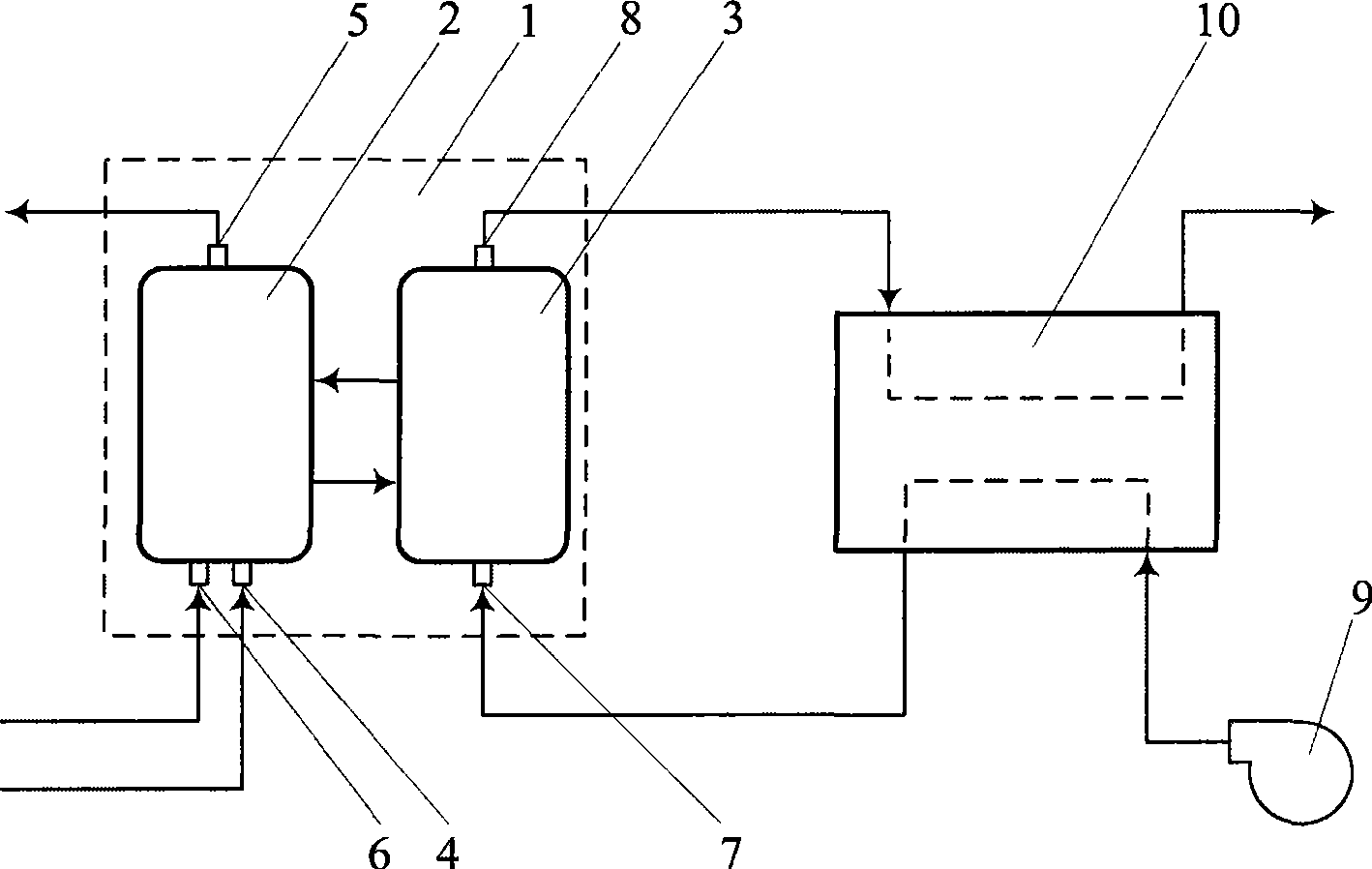
[0082] In this example, three batch regenerative reactors are used. In operation, one batch regenerative reactor is used for reduction operation, one batch regenerative reactor is used for oxidation operation, and one batch regenerative reactor is used for standby.

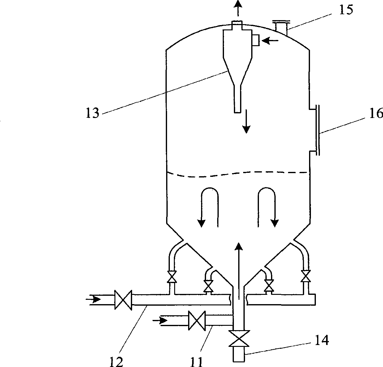
[0083] The structure of the batch regenerative reactor used is as follows figure 2 shown. The batch regenerative reactor is a cylinder with a conical bottom lined with refractory heat storage material. There is a spout air inlet 11 at the bottom of th...

Embodiment 2

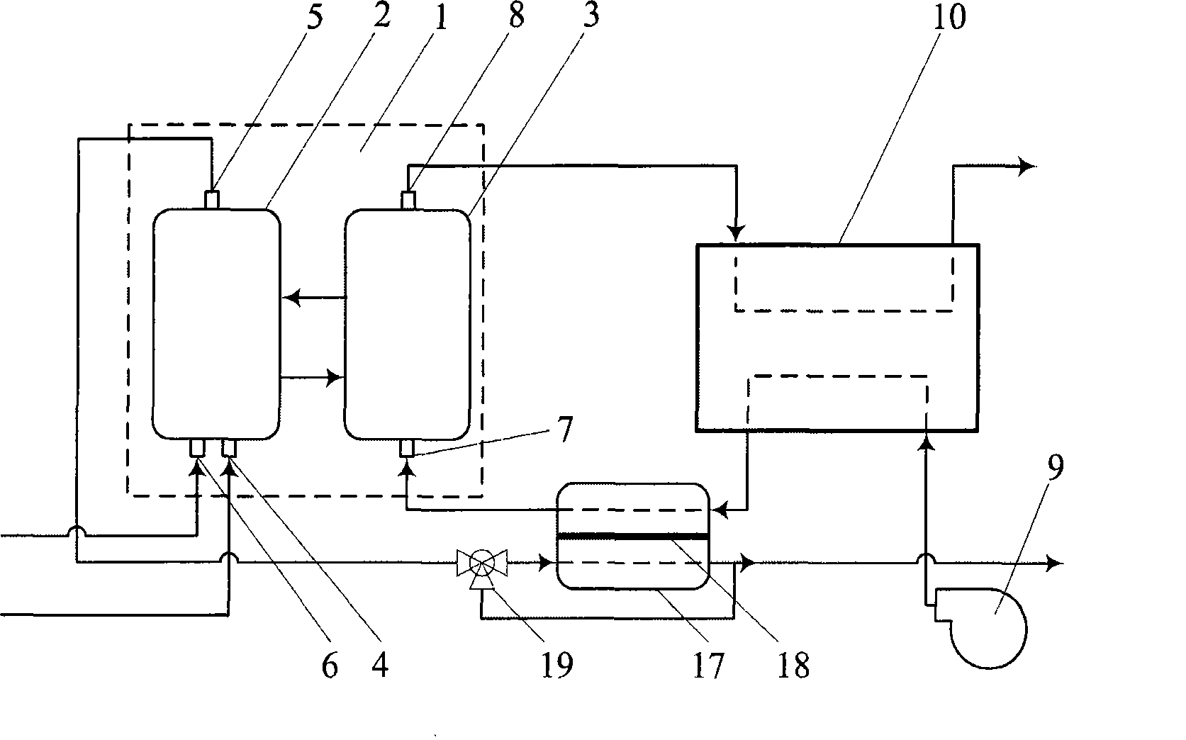
[0090] Such as image 3 As shown, the oxygen separator 17 is a device with a built-in oxygen permeable membrane 18. The oxygen permeable membrane divides the inner space of the oxygen separator 17 into two parts. Flow through one side of the oxygen permeable membrane in the oxygen separator 17, and then send to the gasifier; from the blower, the air preheated by the heat exchange network 10 flows countercurrently through the other side of the oxygen permeable membrane, and then enters the air reaction Air inlet 7 of device 3. The side here is a logical concept, and the actual device is a multilayer film sandwich structure. Before the externally transported gasification agent enters the oxygen separator 17, a diverter three-way valve 19 can be set to allow part of the externally transported gasification agent to bypass the oxygen separator 17. By adjusting the diverter three-way valve 19, the gasification side O can be adjusted. 2 concentration.

[0091] The oxygen permeable...

Embodiment 3

[0094] Such as Figure 4 As shown, the oxygen separator 17 is equipped with a solid oxygen selective adsorbent 20, and the oxygen separator 17 is provided with an air inlet connected to an air source, a waste gas vent, and an external gasification agent pipeline and a chemical looping combustion system for external gasification. The inlet of the gasification agent connected with the gasification agent pipeline, and the outlet of the oxygen-containing oxidizer connected with the gasification agent pipeline of the degasification furnace. Here, the outlet air of the blower is used as the air source. There are two oxygen separators 17 that operate interchangeably. During operation, one of the oxygen separators is fed with air from a blower, cooling the adsorbent bed and allowing the adsorbent to adsorb O 2 , the air after absorbing oxygen is directly discharged to the atmosphere through the exhaust gas vent; in the other oxygen separator, the cold external gasification agent fro...


PUM


Abstract

The invention discloses a method for producing and heating a gas agent which contains carbon fuel and a device thereof, pertaining to the gasification field of fuels containing carbon. Parts of syngas generated by a gasifier is combusted through chemical-looping combustion and the heat generated therefrom is recovered in a heat exchanger network, and under the condition that external H2O and/or CO2 is added, the H2O and CO2 mixed gas at enough high temperature and as large as possible flow is obtained and used as the gas agent; when the gas agent is lack of heat and has too low fractional conversion, O2 is transferred to the gas agent from gas containing the O2 through a peroxy-separator. The gas agent obtained by the method is sent to a ground gasifier or an underground gasifier to react with the fuels containing the carbon, and the syngas containing no N2 is obtained. By adjusting the composition of the gas agent, the composition of the syngas can be adjusted flexibly according to downstream requirements; the discharge of CO2 is low during the whole gasification process; the method relies little on environment and after a gasification system starts and works normally, the syngas can be obtained through the gasification of the fuels containing the carbon so as to provide energy for continuous production, and obtained intermediate material flow is favorable for doping the O2 into the gasifier.

Description

technical field [0001] The present invention relates to the gasification of coal and gasification of other carbon-containing fuels, wherein the carbon-containing fuels include fossil fuels, such as coal, oil sands, and biomass and organic domestic waste. Background technique [0002] The gasification of carbonaceous fuels points to the injection of carbonaceous fuels including O 2 、H 2 O.CO 2 Gasification agent and other substances, under a certain temperature and pressure, make the gasification agent and carbon-containing fuel physically and chemically react to generate synthesis gas. [0003] Taking coal gasification as an example, using air as the gasification agent is a low-cost gasification method, but the syngas contains a lot of N 2 , have adverse effects on subsequent use. with enriched oxygen or pure O 2 As a gasification agent, oxygen-enriched or pure O is produced 2 The cost is higher. [0004] Taking coal as an example, use H 2 O and CO 2 As a gasifying ...

Claims


Application Information

Patent Timeline
IPC IPC(8): C10J3/20
Inventor 张鹏
Owner 张鹏
Why Eureka
Try Eureka