Sacrificial anode and protective cathode-oil-well pump anti-corrosive apparatus

A sacrificial anode protection and anti-corrosion device technology, applied in pumps, pumps with flexible working elements, liquid variable capacity machines, etc. Accident-like, pressure drop manufacturing cost, and the effect of saving consumption

Inactive Publication Date: 2009-04-01
HENAN XINYU PETROLEUM MACHINERY MFG
View PDF0 Cites 18 Cited by
  • Summary
  • Abstract
  • Description
  • Claims
  • Application Information

AI Technical Summary

Problems solved by technology

[0002] At present, the known anti-corrosion technology of oil pumps in oil fields mainly adopts the method of surface coating protection. For example, the surface of the oil well pump barrel is painted with anti-rust paint, the surface of the oil well pump coupling is blackened, or the pump barrel is multi-component infiltrated. The method of spraying the surface of the plunger, the method of using stainless steel instead of ordinary steel for the upper and lower joints of the plunger, the ball seat, and the method of replacing ordinary steel with stainless steel. These methods undoubtedly have a certain protective effect on the anti-corrosion of the oil pump, but the effect is not good. , short protection period, high cost
In industrial enterprises, especially petrochemical enterprises, corrosion is a common problem that affects the normal production of enterprises. Corrosion is a kind of spontaneous and useless consumption that occurs in most metals every moment. The losses and consequences caused by this consumption are very Seriously, it not only wastes a lot of metal raw material resources, but also makes production stop, material flow, equipment cost increase, product quality decrease, service life shorten, pollute the environment, and even cause various accidents

Method used


Image

  • Sacrificial anode and protective cathode-oil-well pump anti-corrosive apparatus
  • Sacrificial anode and protective cathode-oil-well pump anti-corrosive apparatus

Examples


Embodiment Construction

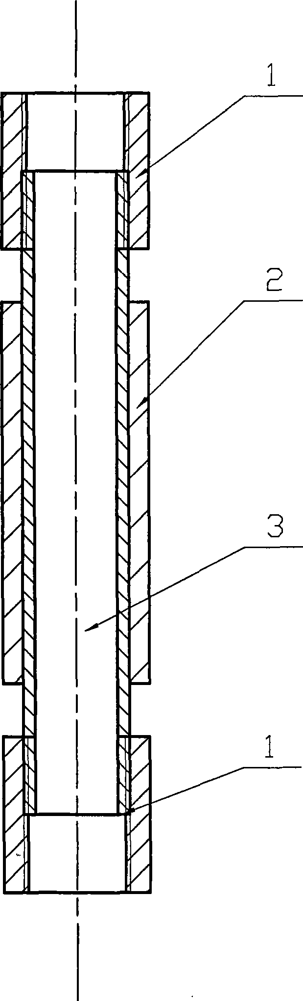
[0010] exist figure 1 Among them, the upper coupling 1 and the pump barrel nipple 3 are connected by threads, the anode 2 is cast on the pump barrel nipple 3 of the oil well pump, and the two ends are processed with threads, which are threadedly connected with the upper and lower couplings 1 respectively.

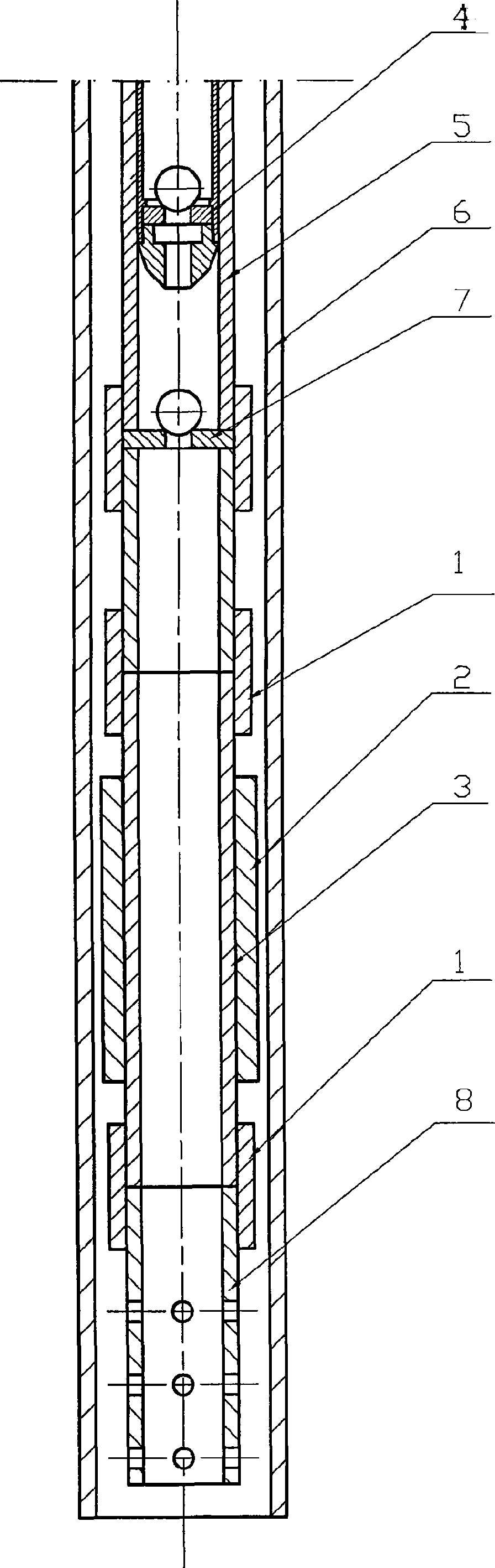
[0011] exist figure 2 In the shown embodiment, the upper coupling 1 is threadedly connected with the oil well pump barrel nipple 3, the anode 2 and the oil well pump barrel nipple 3 are cast together, and the upper end of the oil well pump barrel nipple is threaded with the upper collar 1, Its lower end is threadedly connected with the lower collar, and the lower end of the lower collar is threaded with the oil inlet screen pipe 8. According to calculation and experience, the natural potential formed by the anode of the oil well pump can protect the oil well pump barrel and oil pipe of 50 meters up and down. The installation of the anode of the oil well pump can be compl...


PUM


Abstract

The invention relates to a corrosion resistant device for an oil well pump which utilizes a sacrificial anode to protect a cathode. The corrosion resistant device utilizes the principle of protecting the cathode by sacrificing the anode in electrochemistry and takes zinc, lead, magnesium and other active metals as the anode of the oil well pump. The production method is as follows: the nipple of the oil well pump is processed according to the technical specification of the oil well pump firstly and the length of the nipple is 400mm to 500mm; then the nipple is put into a specially designed rod cavity; magnesium or aluminium or zinc metal blocks are converted into liquid by heating and melting and then cast into the nipple cavity of a special oil well pump; and shaping, thermal insulation, slow cooling, mold unloading and mechanical processing are carried out, a coarse blank is processed into a smooth revolution body, thread at the two ends of the oil well pump is processed, and collars are installed, therefore, the anode assembly of the oil well pump is formed. The instillation method is as follows: during the process of putting down the oil well pump, the anode of the pumping rod is connected in series with the collar at the lower end of the oil well pump and collar is screwed.

Description

Technical field [0001] The invention relates to an oilfield anticorrosion technology, in particular to a technology capable of slowing down the corrosion of oil well pumps. Background technique [0002] At present, the known anti-corrosion technology of oil pumps in oil fields mainly adopts the method of surface coating protection. For example, the surface of the pump barrel is painted with anti-rust paint, the coupling of the oil pump adopts the method of blackening the surface, or the pump barrel adopts multi-component penetration The method of spraying the surface of the plunger, the method of using stainless steel instead of ordinary steel for the upper and lower joints of the plunger, the ball seat, and the method of replacing ordinary steel with stainless steel. These methods undoubtedly have a certain protective effect on the anti-corrosion of the oil pump, but the effect is not good. , the protection period is short and the cost is high. In industrial enterprises, e...

Claims


Application Information

Patent Timeline
Patent Type & Authority Applications(China)
IPC IPC(8): C23F13/06F04B47/00
Inventor 廖大林杜振宇杨新生
Owner HENAN XINYU PETROLEUM MACHINERY MFG
Why Eureka
Try Eureka