
Solar assembly test method and device thereof

A technology for solar modules and testing methods, which is applied to measurement devices, single semiconductor device testing, non-contact testing, etc., can solve problems such as one-time completion of the tested site, and achieve the effect of shortening the testing process and simplifying the testing process.

Inactive Publication Date: 2009-04-01
CSI CELLS CO LTD
View PDF1 Cites 14 Cited by
  • Summary
  • Abstract
  • Description
  • Claims
  • Application Information

AI Technical Summary

Problems solved by technology

[0004] However, the above tests on components are applicable to the daily maintenance of components after the power station is established. In the feasibility demonstration stage before the construction of the power station, the first consideration is the selection of the location of the power station and the number of components required to form the power station. Among them, the location of the power station Natural and geographical conditions need to be considered: meteorological data (solar radiation energy resources, etc.), longitude, latitude, altitude, geology, earthquake, flood, temperature, wind speed, longest rainy days in a year, thunderstorms, sandstorms, hail, air cleanliness (acid rain ), environmental impact, etc., according to the local solar irradiance (as far as the surface of our earth is concerned, the maximum sunlight intensity is 1000w / m 2 , about 710w / m on average 2 ), annual sunshine amount = average sunshine intensity × annual sunshine time, calculate the demand of solar cells; at the same time, according to the local solar radiation, meteorological and geographical data, system efficiency and requirements, load daily power consumption to estimate the solar cell Capacity; on the other hand, due to changes in local climate or load, it is impossible to detect whether the established power station still meets the original design requirements, whether it can be expanded according to local natural conditions, etc., with the current test methods and test devices. The test site is completed once, and the measured data needs to be returned to the base for repeated calculations.

Method used


Image

  • Solar assembly test method and device thereof
  • Solar assembly test method and device thereof

Examples


Embodiment 1

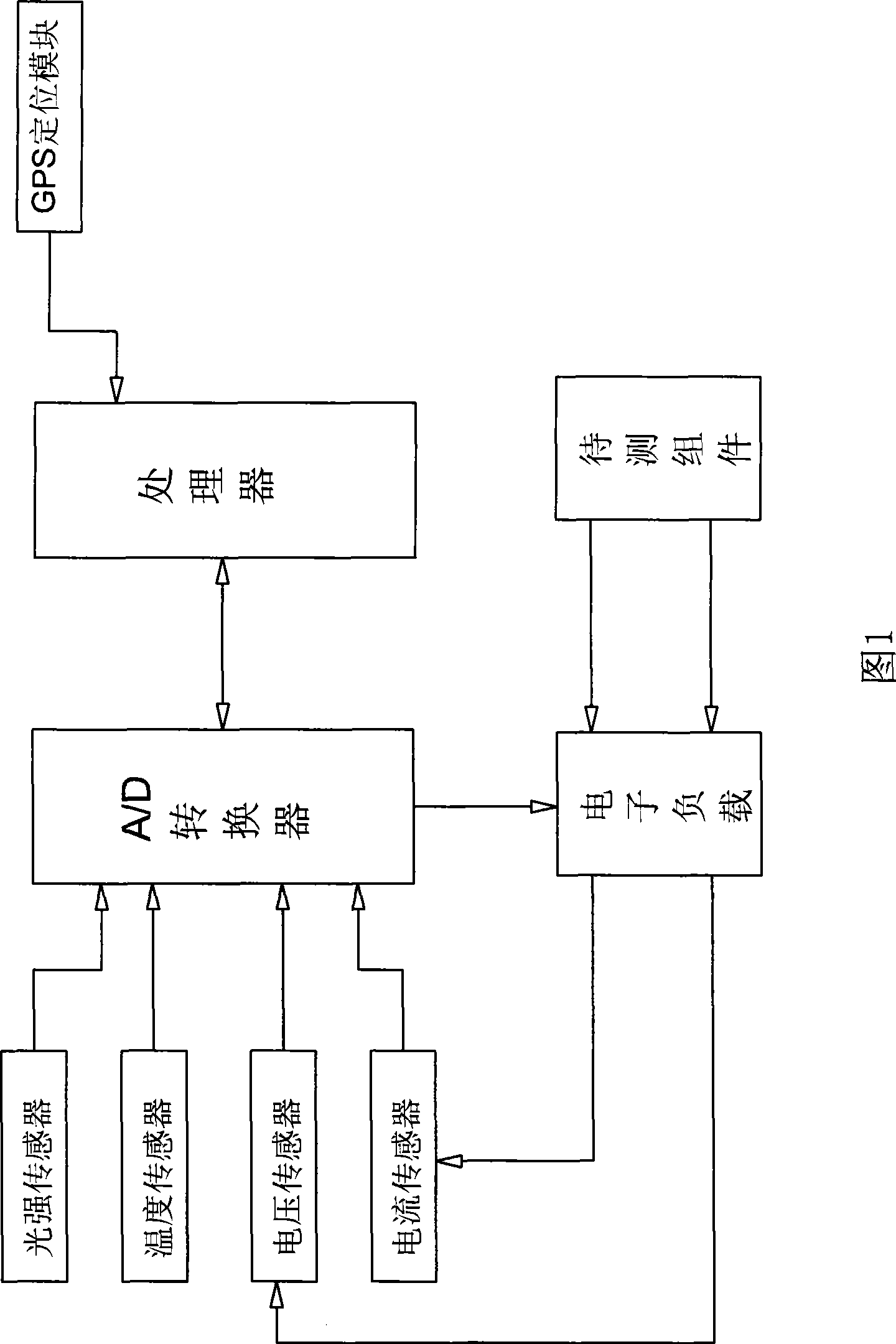
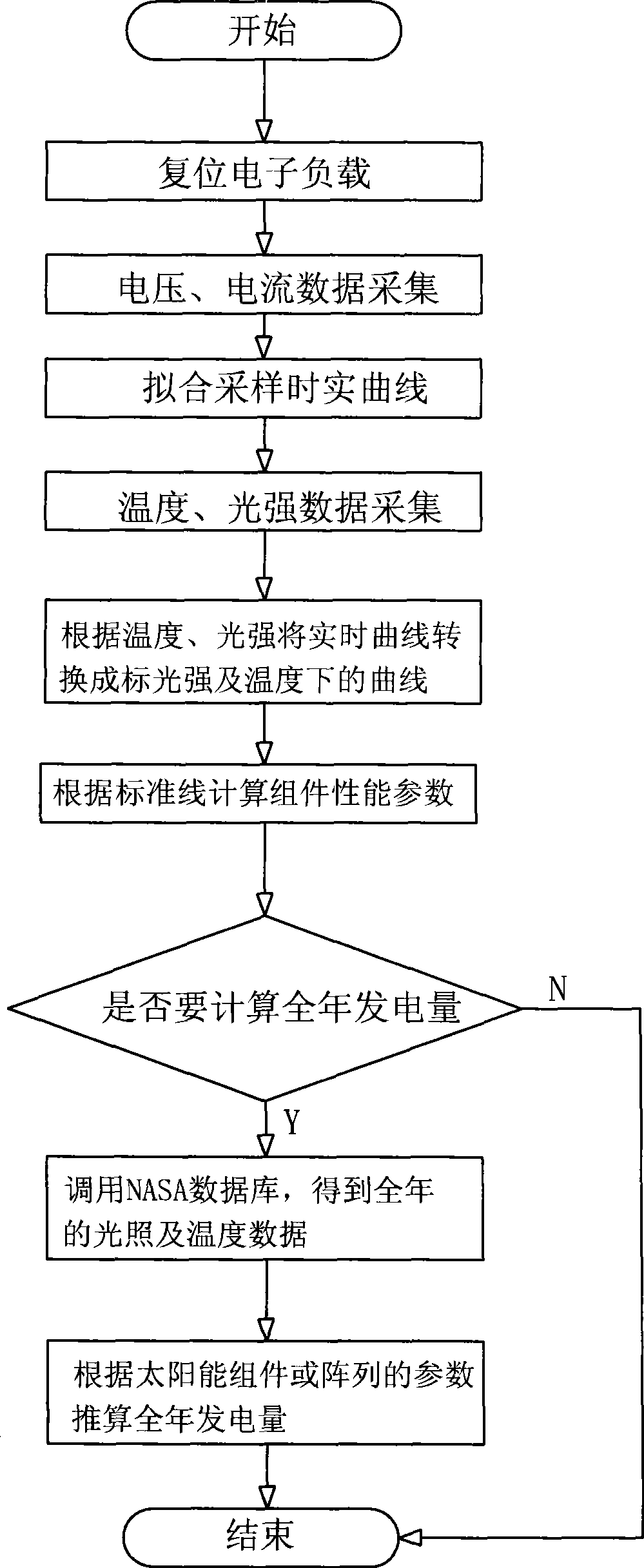
[0022] Embodiment one: referring to Fig. 1, shown in Fig. 2, a kind of solar module testing method comprises the following steps:

[0023] a. Use the local sunlight as the detection light source to measure the performance parameters of the solar modules;

[0024] b. Obtain the longitude and latitude of the measured place through the GPS global positioning system;

[0025] c. According to the longitude and latitude in step b, call the meteorological data in the NASA database to obtain the annual illumination and temperature data of the measured place;

[0026] d. Combining the data obtained in step a and step c, calculate the annual power generation of the solar module in the measured place;

[0027] In order to complete the above test method, a solar module testing device is adopted, as shown in Figure 1, including a processor, an A / D converter, an electronic load, a GPS positioning module and a sensor group, and the sensor group includes a light intensity sensor, temperatur...


PUM


Abstract

The invention discloses a method for testing a solar energy component and a device thereof. The invention is characterized in that: a, performance parameters of the solar energy component are measured; b, longitude and latitude of the measured place are obtained by a GPS positioning system; c, meteorological data in the NASA database is transferred according to the longitude and the latitude, so as to obtain the data of annual illumination and temperature; d, annual generated energy of the component at the measured place is calculated according to the step a and the step c; the device comprises a processor, an A / D convertor, an electronic load and a sensor group, wherein, the processor receives the signals measured by the sensor group by the A / D convertor, the electric load which is connected on the sensor is taken as an artificial load of the measured component; the device is characterized in that the device also comprises a GPS positioning module which is connected with the processor by the data interface on the processor. The invention utilities the detection data of the GPS positioning system to transfer the NASA meteorological data and realizes the prediction of annual generated energy of the measured component, thus being beneficial to the construction and maintenance detection of the power station.

Description

technical field [0001] The invention relates to an electrical testing method and a device thereof, in particular to a testing method for testing the performance of a solar module and a testing device for realizing the testing method. Background technique [0002] At present, fossil energy is gradually exhausted. Due to the universality, longevity and cleanness of sunlight, solar power generation will be an important source of future energy composition. Photovoltaic power station is a kind of energy production device that utilizes the photovoltaic characteristics of solar cells, receives radiated sunlight, generates photogenerated current, and supplies various loads through adjustment, transformation, storage, and distribution. Its basic components are: ① solar cell array ; ② storage equipment; ③ charge and discharge, inverter control mediator; ④ transmission, transmission, distribution equipment. Among them, the solar battery array (also known as solar modules), composed of...

Claims


Application Information

Patent Timeline
IPC IPC(8): G01R31/00G01R31/265G01R21/133
Inventor 章灵军闫广川
Owner CSI CELLS CO LTD
Learn More