Seal connecting method of porous ceramic plate column

A technology of porous ceramic plate and connection method, which is applied in heating methods, household heating, space heating and ventilation details, etc., can solve the problems of increased cost, complicated installation, low molding efficiency, etc., to speed up construction progress and improve reliability. performance, reducing reliability

Inactive Publication Date: 2009-04-15
曹树梁
View PDF6 Cites 11 Cited by
  • Summary
  • Abstract
  • Description
  • Claims
  • Application Information

AI Technical Summary

Problems solved by technology

Both have the following disadvantages: 1. The metal tube-sheet heat collector mainly adopts materials such as copper and aluminum, and the structure and manufacturing process of the vacuum glass tube heat collector are relatively complicated. high
2. Both of them use black sunlight absorbing paint coated at low temperature. Under the long-term sunlight, there will be a certain degree of aging to attenuate the sunlight absorption rate, the metal is easy to corrode, and the vacuum degree in the vacuum glass tube will gradually decrease. Significant Cause of Lifetime and Efficiency Issues
[0012] 1. Usually the temperature difference between the inside and outside of the greenhouse is about 30°C, but when the solar collector is air-dried, the temperature difference between the inside and outside can exceed 120°C. In contrast, the heat collection efficiency of the "solar chimney" is low, but the existing solar collectors The cost of the heater is too high, and the heat collector of the vacuum glass tube is a blind tube closed at one end, which makes it difficult to form a smooth air flow, which also makes the application difficult
[0013] 2. The chimney with a diameter of 130m and a height of 1000m is currently the tallest man-made building, and the technical and construction difficulties in the construction process may result in a higher cost
[0017] 2. The exploration co

Method used


Image

  • Seal connecting method of porous ceramic plate column
  • Seal connecting method of porous ceramic plate column
  • Seal connecting method of porous ceramic plate column

Examples


Embodiment

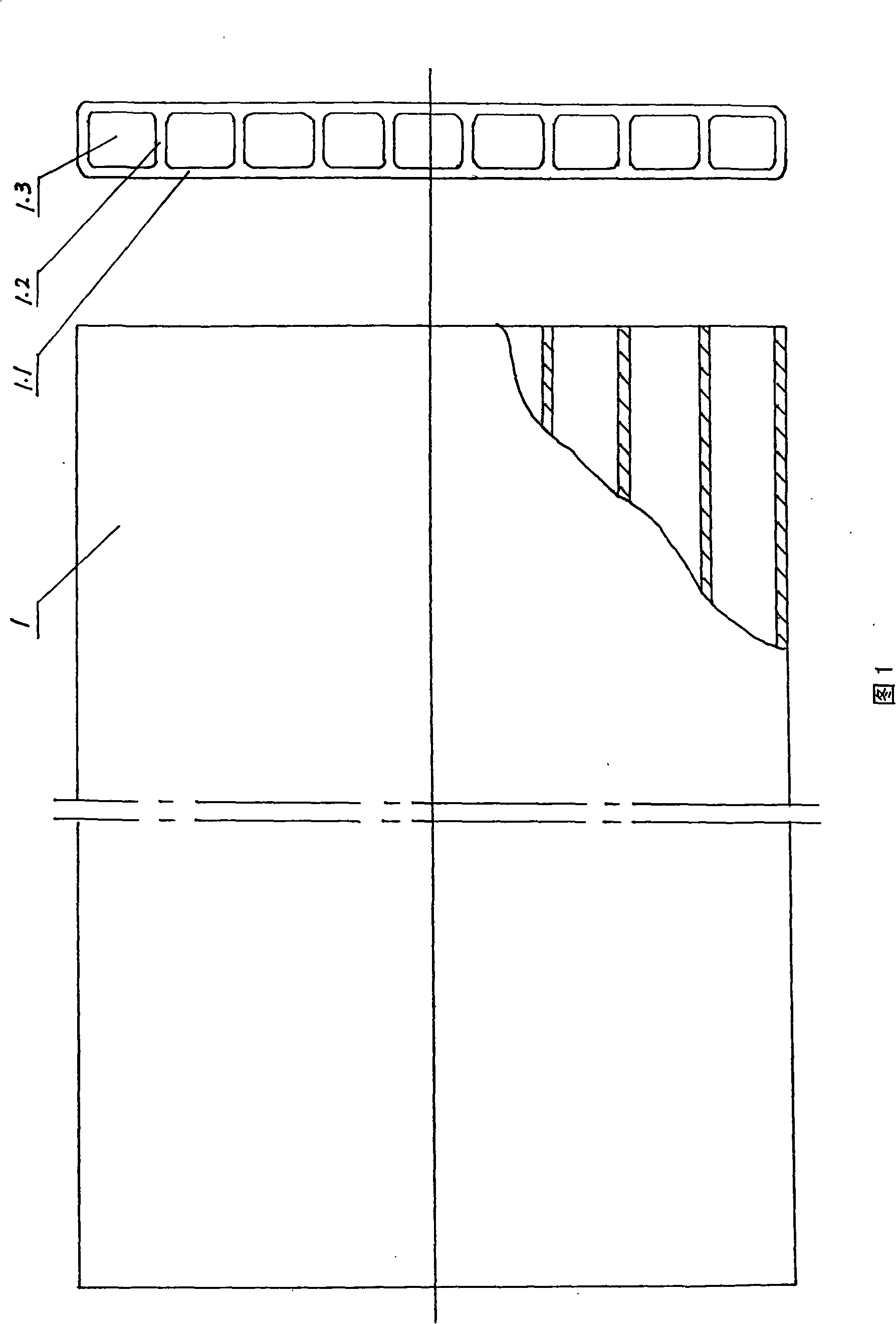
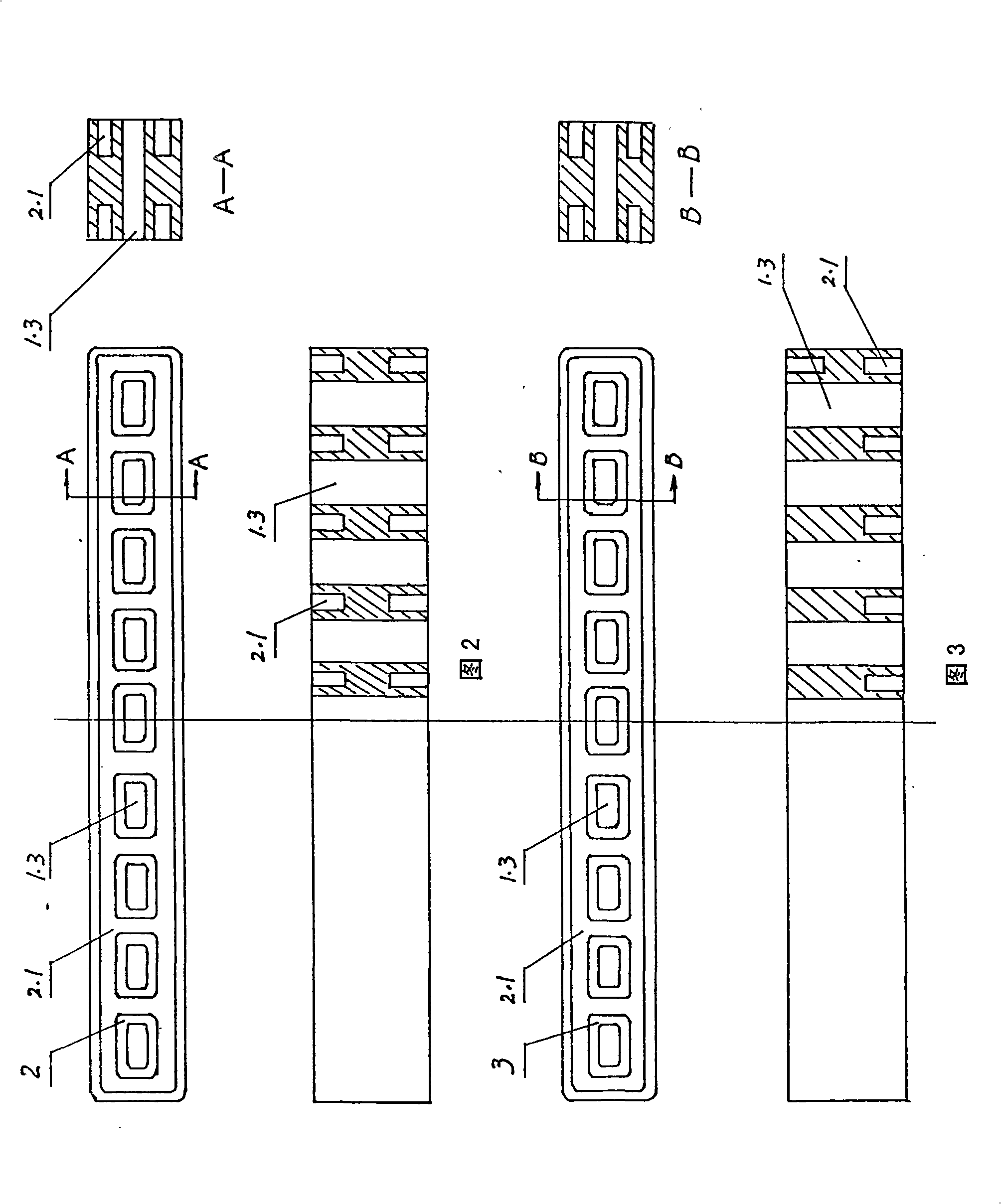
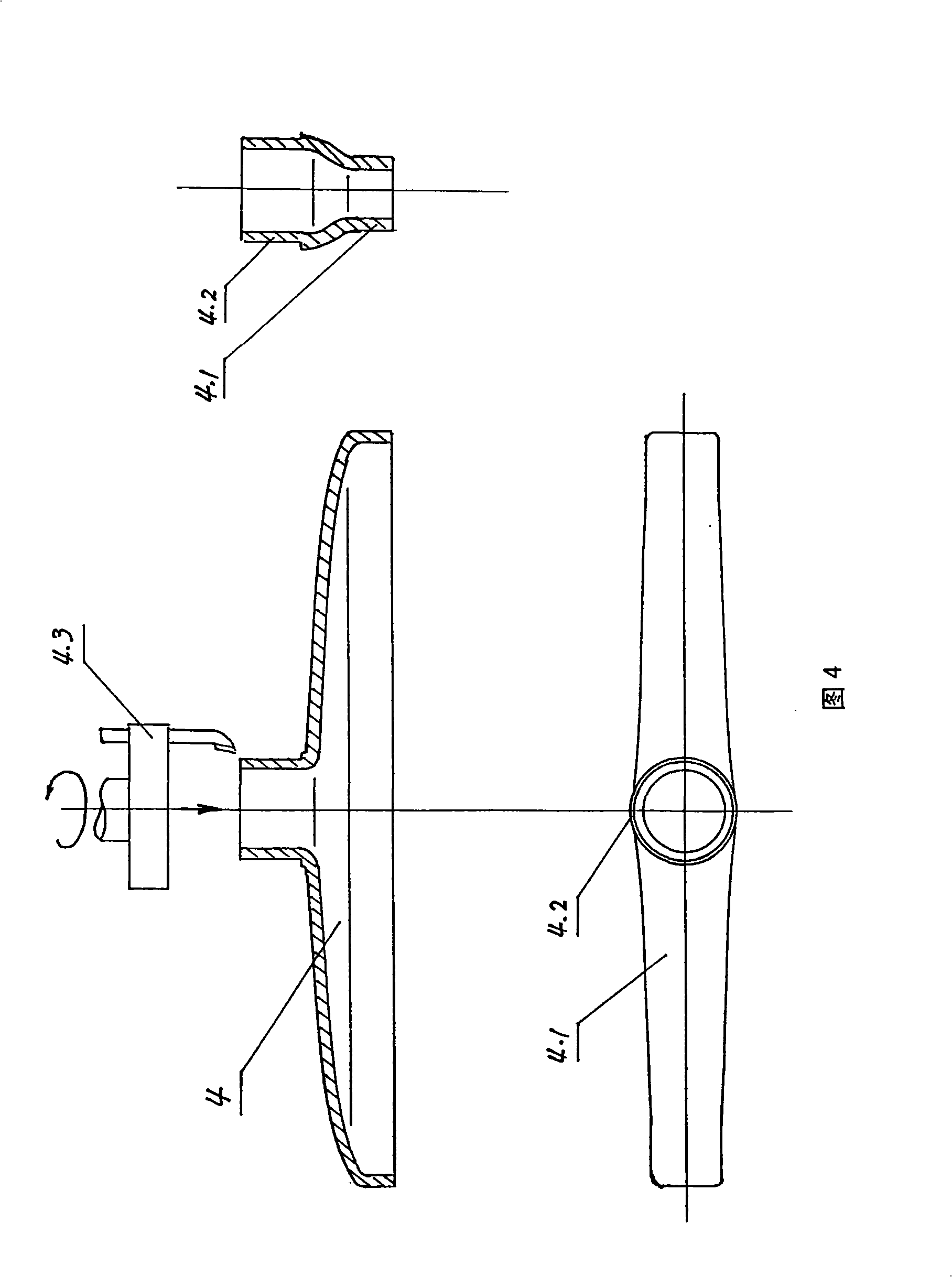
[0058] 1. The length of the porous ceramic plate is 1500mm, the width is 610mm, the total thickness is 26mm, the outer wall thickness is 2.6mm, and the partition wall thickness is 4.3mm. The centerline of the outer wall and the centerline of the partition wall in the cross-section of the plate coincide, the groove width is 6-8mm, the annular groove width of the ∪-type transitional socket interface is 8mm, the annular outer wall thickness of the converging port is 5mm, the outer diameter of the circular pipe is 53mm, the inner diameter is 40mm, and the silicon Rubber is used as a sealing and connecting agent, and the above-mentioned porous ceramic plates, ∪-shaped socket interface, ∪-shaped transitional socket interface, and collection ports are combined into a column of porous ceramic plates.

[0059] 2. The tandem of porous ceramic plates as described in Example 1, the width of the porous ceramic plates is 800 mm, and high polymer cement is used as the sealing agent.

[0060]...


PUM


Abstract

The invention provides a sealing connection method used for longitudinal lines of porous ceramic plates, comprising the steps as follows: normal ceramics is used as raw material; a porous ceramic plate biscuit with the substrate of normal ceramic is prepared by a vacuum extrusion method; subsequently, the surface of the porous ceramic biscuit is covered by black porcelain slurry and sintered to be a black porcelain composite porous ceramic plate; alternatively, the normal ceramics raw material is mixed with the black porcelain raw material to prepare the wholly black porous ceramic plate; ceramic material, inorganic material, organic material and metal material are used for preparing a U-shaped connection interface, a U-shaped transitional connection interface and a collecting port which are combined into the longitudinal lines of the porous ceramic plates by a sealing adhesive; the fluid in a passage is sealed by the sealing adhesive in the three groups of parallel surfaces in U-shape so as to lead all parts to form convenient, economical and reliable sealing and connection; and the longitudinal lines of the porous ceramic plate can be used for collecting solar energy, far-infrared radiation and heat dissipation of building heating.

Description

(1) Technical field [0001] The invention relates to the technical field of ceramic manufacturing and application of ceramic products, in particular, adopts the method of ∪-shaped sealing connection to combine porous ceramic plates into a column of porous ceramic plates. (2) Background technology [0002] After nearly 200 years of continuous accelerated mining, fossil fuel resources such as coal, oil, and natural gas have been gradually exhausted. Now we must find at least one new large-scale alternative energy within a limited time. Like nuclear fusion, deep-sea combustible hydrates, space solar power plants, low-cost solar cells, etc., the extensive application of low-cost, long-life solar collectors can also form new large-scale alternative energy sources. [0003] The current consensus in the scientific community is that the total amount of solar radiant energy reaching the earth's land surface is tens of thousands of times greater than the total amount of energy consumed...

Claims


Application Information

Patent Timeline
IPC IPC(8): F24J2/00F24J2/46F24J2/48F24D19/00
CPCY02E10/40
Inventor 曹树梁许建华蔡滨王启春石延岭许建丽谷胜利杨玉国修大鹏
Owner 曹树梁
Why Eureka
Try Eureka