Photoetching objective lens

A lithography objective lens and lens technology, applied in the field of lithography objective lens, can solve the problem that the positioning accuracy and resolution of the fine pattern printed board are reduced, the liquid photoresist is stained on the master plate, and the resolution cannot be very good. High problems, to achieve the effect of large one-time exposure area, convenient and practical one-time exposure area, and simple structure

Inactive Publication Date: 2009-04-15
GUANGDONG UNIV OF TECH
View PDF0 Cites 2 Cited by
  • Summary
  • Abstract
  • Description
  • Claims
  • Application Information

AI Technical Summary

Problems solved by technology

However, the development of printed board technology has made the limitations of contact imaging more and more obvious: First, with the continuous thinning of the conductors and line spacing of large-area printed boards, large-area uneven contact is likely to cause line width and clear edges The change of the degree makes the positioning accuracy and resolution of the fine graphic printed board decrease, resulting in the production of the printed board being scrapped due to open circuit and short circuit; secondly, multiple exposures in the production process, that is, the repeated production of the bottom plate and the printed board Contact will cause impurity contamination, shorten the life of the bottom plate, and cause problems such as liquid photoresist being stained on the bottom plate
The exposure of the proximity exposure method leaves a certain space between the base plate and the substrate. Although this method avoids various problems caused by the contact between the base plate and the substrate, it is affected by the diffraction of the base plate, so the resolution is impossible. do it very high

Method used


Image

  • Photoetching objective lens

Examples


Embodiment

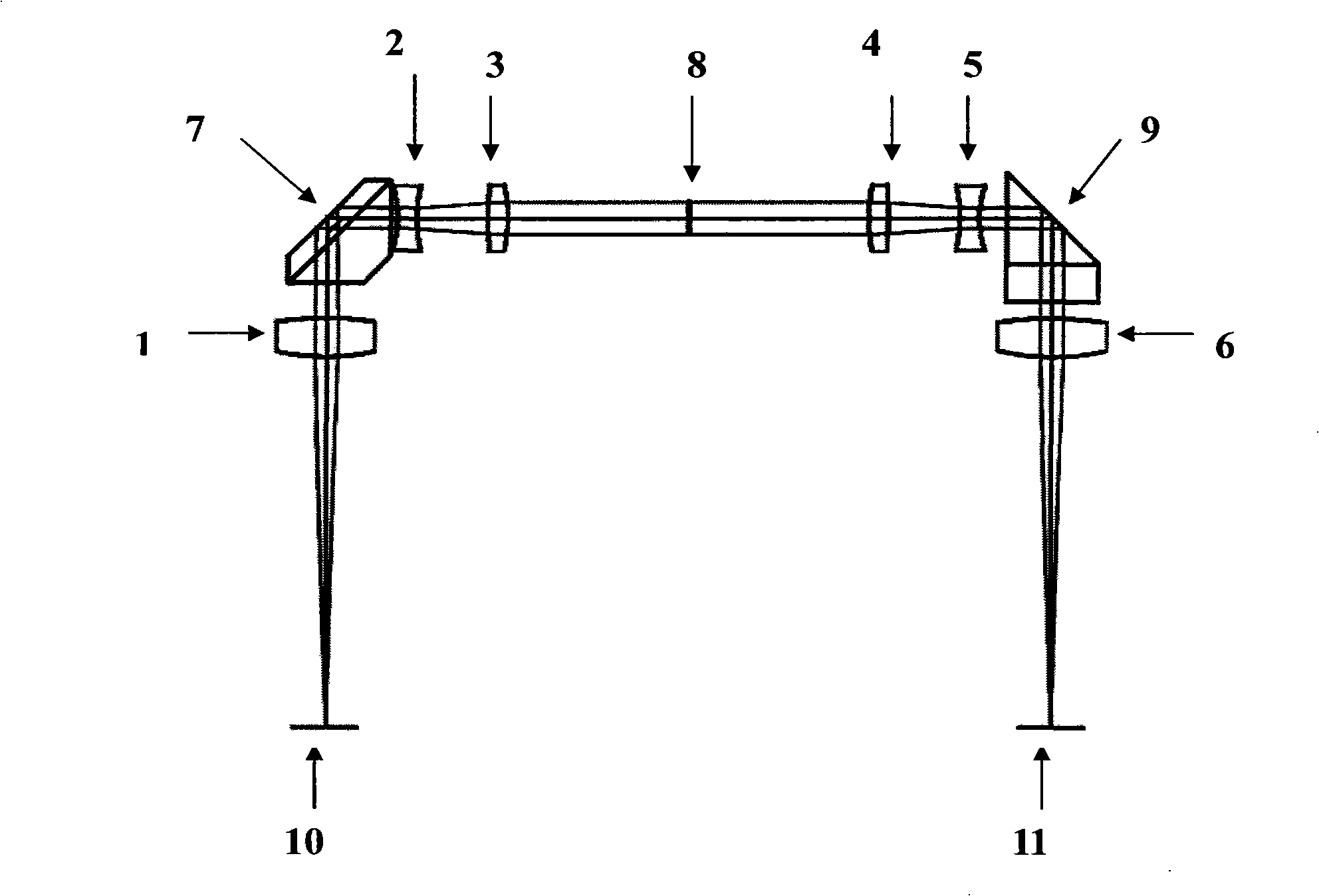
[0016] The structure diagram of the present invention is as figure 1 As shown, it includes an object plane 10 installed in sequence, a first lens 1, a first prism 7 for changing the direction of the object and the image to make the direction of the object and the image consistent, the second lens 2, and the third lens 3 , diaphragm 8, fourth lens 4, fifth lens 5, second prism 9 for changing the direction of object and image, making the direction of object and image consistent, sixth lens 6, image plane 11, wherein the first The lens 1 has the same structure as the sixth lens 6 , the second lens 2 has the same structure as the fifth lens 5 , and the third lens 3 has the same structure as the fourth lens 4 .

[0017] In this embodiment, the above-mentioned first prism 7 is a roof prism. The above-mentioned second prism 9 is a rectangular prism.

[0018] In addition, the middle section of the diaphragm 8 is a parallel optical path, and components such as beam splitters can be i...


PUM


Abstract

The invention discloses a photolithographic objective lens which comprises object plane (10), a first lens (1), a first prism (7) which is used for changing directions of an object and an image and causing the directions of the object and the image of the prism to be identical, a second lens (2), a third lens (3), a diaphragm (8), a fourth lens (4), a fifth lens (5), a second prism (9) which is used for changing directions of the object and the image and causing the directions of the object and the image of the prism to be identical, a sixth lens (6) and an image surface (11), all of which are arranged in sequence; wherein, the structure of the first lens (1) is complete identical with the structure of the sixth lens (6), the structure of the second lens (2) is complete identical with the structure of the fifth lens (5), and the structure of the third lens (3) is complete identical with the structure of the fourth lens (4). The photolithographic objective lens adopts six lenses and two prisms to form a double telecentric optical path structure in which both the object space and the image space are telecentric, and the structure avoids magnification ratio change caused by the defocusing of a mask and a substrate, and causes the relative illumination to nearly reach 100%. The photolithographic objective lens has the advantages of high resolution, great focal depth, small distortion, simple structure, large single exposure area, convenience and practicality.

Description

technical field [0001] The invention relates to a photoetching objective lens for laser exposure of printed circuit boards, which belongs to the modification technology of the photoetching objective lens. Background technique [0002] Conventional exposure of printed circuit boards usually adopts a contact or proximity exposure method. Both of these methods have defects. Among them, the contact exposure method needs a photographic original plate, and the production base and the printed board must be in full contact during exposure. Corresponding shadows are formed on the board due to photochemical reactions. However, the development of printed board technology has made the limitations of contact imaging more and more obvious: First, with the continuous thinning of the conductors and line spacing of large-area printed boards, large-area uneven contact is likely to cause line width and clear edges The change of the degree makes the positioning accuracy and resolution of the ...

Claims


Application Information

Patent Timeline
Patent Type & Authority Applications(China)
IPC IPC(8): G02B13/00G03F7/20
Inventor 李文静周金运林清华
Owner GUANGDONG UNIV OF TECH
Why Eureka
Try Eureka