Axial plunger pump or motor

An axial piston pump and motor technology, applied in the field of hydraulic pump or motor device, can solve the problems of complex structure and process, high cost, large size, etc., to achieve improved oil absorption performance, reduced oil filtration accuracy requirements, friction and The effect of leakage reduction

Inactive Publication Date: 2010-12-22
朱荣辉
View PDF7 Cites 4 Cited by
  • Summary
  • Abstract
  • Description
  • Claims
  • Application Information

AI Technical Summary

Problems solved by technology

However, this kind of pump depends on the swing cylinder to change the variable size, and the external dimension is relatively large; the deflection between the rotor and the power shaft makes the outside

Method used


Image

  • Axial plunger pump or motor
  • Axial plunger pump or motor
  • Axial plunger pump or motor

Examples


Embodiment Construction

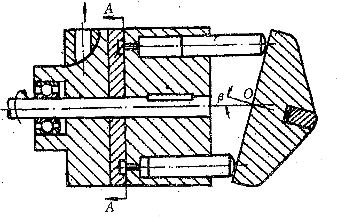
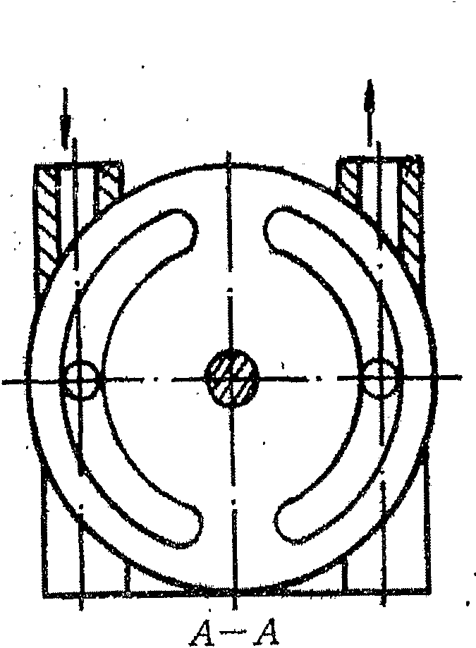
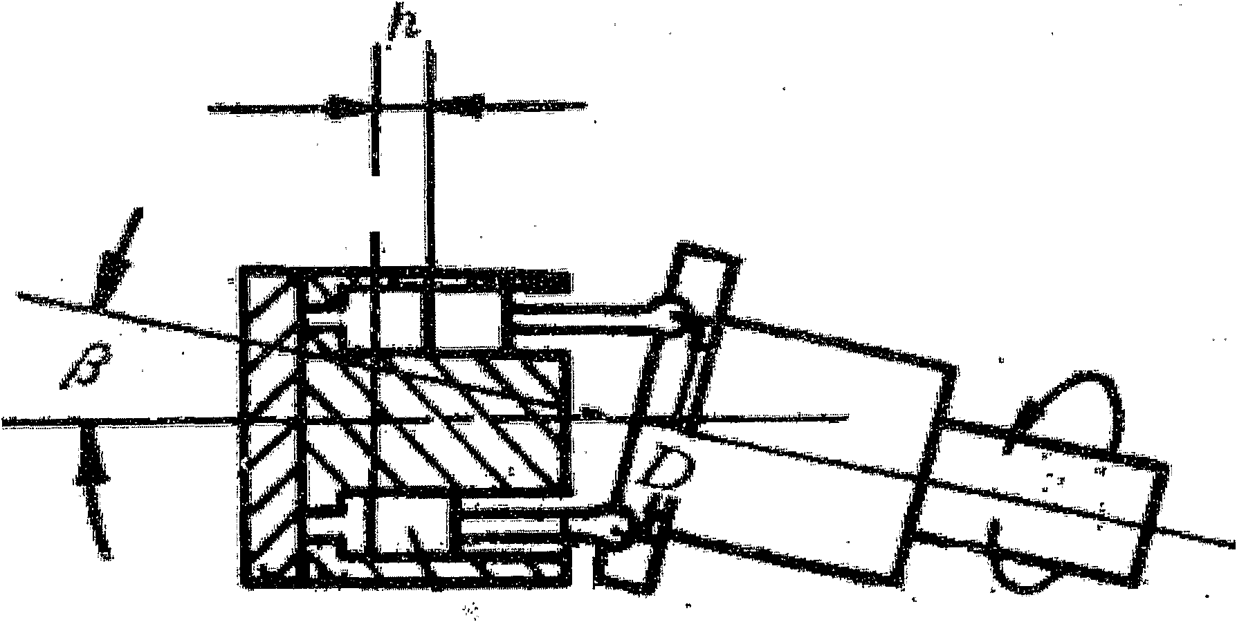
[0056] see Figure 4 As shown, the axial piston pump or motor of the present invention mainly includes: a housing 1; a main shaft 4, which is rotatably supported on the housing 1; a rotor cylinder 14 with a plurality of plunger holes, which is combined on the main shaft 4 , which is driven by the main shaft 4 to rotate around the main shaft axis 41, and the rotor cylinder 14 has an oil distribution end face; the oil distribution plate 15 is matched with the oil distribution end face of the rotor cylinder 14; A plurality of plunger holes of the cylinder body 14 are arranged axially opposite to each other, and can rotate around the swash plate axis 91 forming an angle with the main shaft axis 41; a plurality of plunger assemblies 10, one end of which is hinged on the end surface of the swash plate 9 , the other end is slidingly set in the plunger hole of the rotor cylinder 14; the constant velocity universal joint 11 is set between the swash plate 9 and the main shaft 4, and the...


PUM


Abstract

An axial plunger pump or motor includes a casing (1), a main shaft (2), a cylinder (14), a swash plate (9), some plunger assemblies (10). A constant velocity universal coupling (11) transfers torque between the main shaft and the rotating swash plate, and then the main shaft and the swash plate rotate around the axes of the main shaft or the swash plate respectively. The conversation between the hydraulic energy and the rotation mechanical energy is realized.

Description

technical field [0001] The invention relates to a hydraulic pump or motor device in a hydraulic machine, in particular to an axial piston pump or motor. Background technique [0002] In hydraulic machinery, the hydraulic pump or motor is the heart of the hydraulic device. Theoretically speaking, hydraulic pumps and motors can be switched to each other, and there are only some differences in some parts. Therefore, only the design of the pump is discussed in the description of the present invention, and the structure of the motor is basically the same. The plunger pump is more and more widely used in construction machinery because of its high efficiency, high pressure and easy variable adjustment. [0003] Piston pumps are divided into axial plunger pumps and radial plunger pumps according to the direction of plunger stroke, and axial plunger pumps are divided into swash plate plunger pumps and inclined axis plunger pumps according to the mechanism of motion conversion. Pum...

Claims


Application Information

Patent Timeline
IPC IPC(8): F04B39/00
CPCF04B1/128F04B1/2078F04B1/146F04B1/124F16D3/16F04B1/2064F04B1/2035F04B1/2085F04B1/24F04B1/122F04B1/2042F05B2260/79F05B2250/232F05B2240/20F05B2240/50F05B2210/11Y10S417/00
Inventor 朱荣辉
Owner 朱荣辉
Why Eureka
Try Eureka