Double-crank frame type flying shears

A flying shear, frame type technology, applied in the direction of shearing device, shearing machine equipment, accessories of shearing machine, etc., can solve the problems of complex structure and movement, low production efficiency and high manufacturing cost, and achieve easy manufacturing and maintenance. , The effect of small structure size and simple structure

Inactive Publication Date: 2009-04-29
刘海昌 +2
View PDF1 Cites 13 Cited by
  • Summary
  • Abstract
  • Description
  • Claims
  • Application Information

AI Technical Summary

Problems solved by technology

Compared with the flying shear, the speed of the static shear unit is low, the production efficiency is low, and the benefit is low
The widespread use of static shears is a great waste of resources
[0004] Chinese invention paten...

Method used


Image

  • Double-crank frame type flying shears
  • Double-crank frame type flying shears
  • Double-crank frame type flying shears

Examples


Embodiment Construction

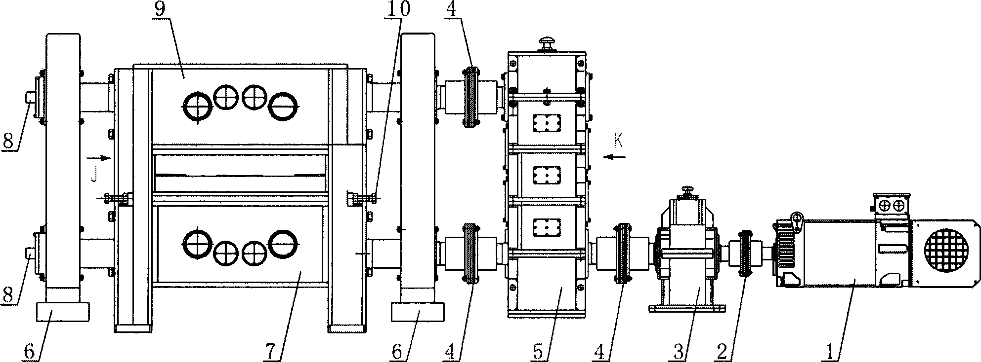
[0026] figure 1 Instructions marked in: Motor 1, No. 1 Coupling 2, Reducer 3, No. 2 Coupling 4, Gear Distribution Box 5, Fixed Base 6, Lower Tool Holder 7, Encoder 8, Upper Tool Holder 9, Blade gap adjustment device 10'.

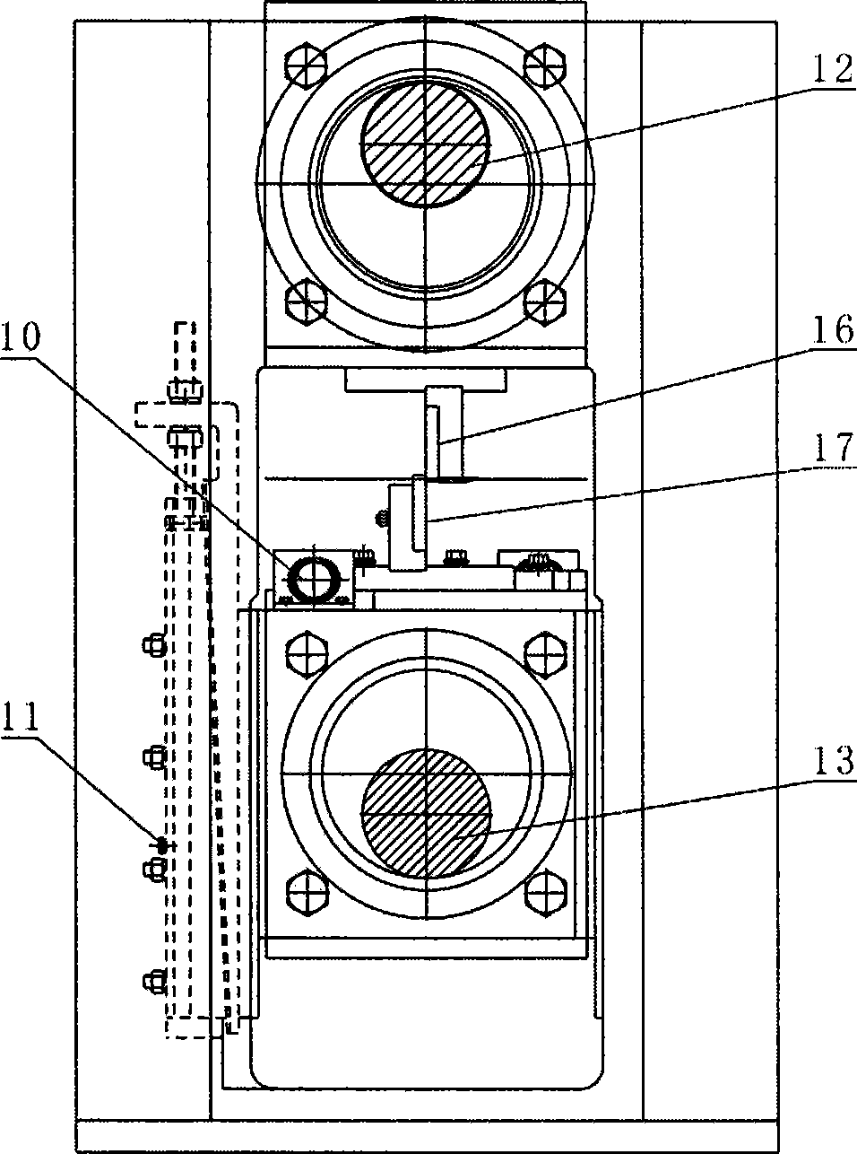
[0027] figure 2 Explanation of middle marks: slideway gap adjustment device 11, upper tool seat crankshaft 12, lower tool seat crankshaft 13, upper blade 16, lower blade 17.

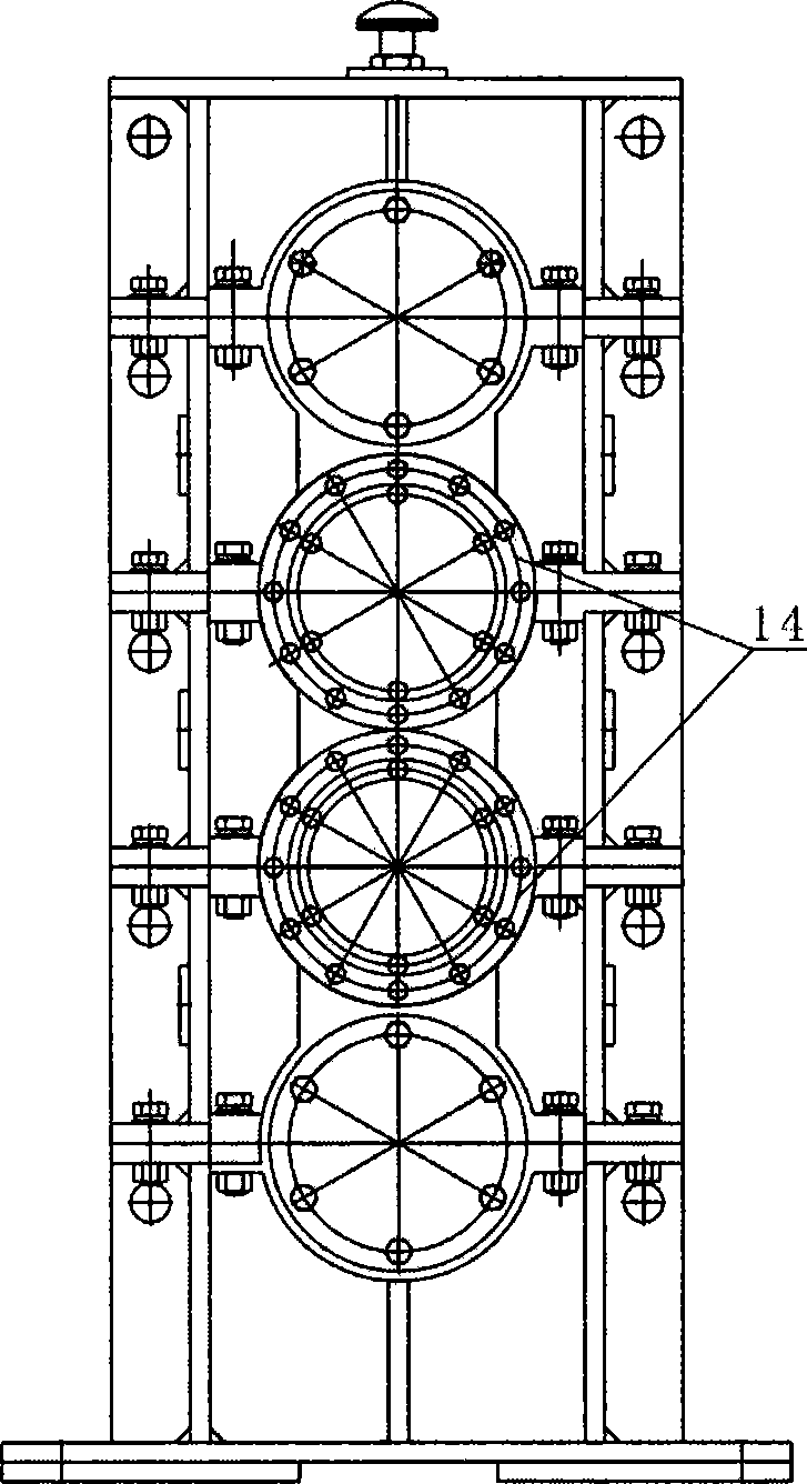
[0028] image 3 Instructions marked in: gear distribution box gear backlash adjustment device 14.

[0029] Figure 4 Instructions marked in: primary and secondary gear mechanism 15.

[0030] Depend on figure 1 , figure 2 , image 3 , Figure 4 It can be seen that the double crank frame type flying shear of the embodiment of the present invention mainly consists of motor 1, No. 1 shaft coupling 2, speed reducer 3, No. 2 shaft coupling 4, gear distribution box 5, fixed support 6, lower Knife seat 7, slideway clearance adjustment device 11, upper knife seat 9, blade clearance ...


PUM


Abstract

The invention discloses a double crank frame type flying shear mainly used for a traverse production line which carries out continuous and synchronous cutting to black and non-ferrous metal cold and hot belt materials in the metallurgy. The flying shear drives a reducer and a gear distribution box by the driving of a motor, two crankshafts of a shearing mechanism are driven to drive an upper cutter block and a lower cutter block to carry out planar motion, and the vertical and horizontal planar motion ensures the synchronized motion while completing the shearing motion to the workpiece. The flying shear has the advantages of lighter weight, delicate and simple structure, high strength, flexible and convenient adjustment, easy manufacture and repair, smooth and straight incision, high cutting speed, high cutting precision, and the like.

Description

technical field [0001] The invention discloses a novel double-crank frame-type flying shear, which is mainly used in a cross-cutting production line for continuous and synchronous cutting of black (and non-ferrous) metal hot and cold plates and strips in the metallurgical industry. Background technique [0002] The flying shear refers to a shearing machine that shears the rolled piece transversely and can be cut into a fixed length. It not only needs to meet the requirements of various fixed lengths, but also needs to meet the requirements of shearing accuracy and productivity of the production line. [0003] Since the introduction of modern continuous rolling technology of plate and strip in the 1970s, flying shears have always been one of the important equipment introduced in large iron and steel enterprises in my country. With the rapid development of the national economy, the demand for ferrous (and non-ferrous) metal hot and cold-rolled strips is also increasing, and u...

Claims


Application Information

Patent Timeline
IPC IPC(8): B23D25/08B23D33/00
Inventor 刘海昌刘洋马卫平
Owner 刘海昌
Why Eureka
Try Eureka