
Pulse ultra wideband receiver

A pulse ultra-wideband and receiver technology, applied in electrical components, transmission systems, etc., can solve the problems of not reaching the UWB sampling rate, deterioration of energy consumption per bit of the circuit, reduction of bandwidth W, etc., to reduce power consumption and complexity , Conducive to chip implementation and reduce the difficulty of implementation

Inactive Publication Date: 2009-05-06
SHENZHEN OUDMON TECH
View PDF0 Cites 11 Cited by
  • Summary
  • Abstract
  • Description
  • Claims
  • Application Information

AI Technical Summary

Problems solved by technology

However, in order to maintain compatibility with the narrowband system, the UWB transmission system must use a low power spectral density, wideband narrow pulse signal, and its bandwidth W cannot be reduced like a narrowband system. The sampling rate fs=2W, according to the circuit theory, this will lead to a very high power consumption P
However, the data rate Rb of more actual transmission systems cannot reach as high as the UWB sampling rate (such as above 1 GHz), which leads to a high number of receiver flips per transmission of 1 bit data, making the circuit's unit bit energy consumption Ec deterioration
It can be seen that synchronous sampling reception is not suitable for UWB transmission systems, especially in low-speed applications of Rb<

Method used


Image

  • Pulse ultra wideband receiver
  • Pulse ultra wideband receiver
  • Pulse ultra wideband receiver

Examples


Embodiment Construction

[0025] The present invention will be further described in detail below through specific embodiments and in conjunction with the accompanying drawings.

[0026] The present invention comprehensively considers communication theory and circuit theory, and combines the characteristics of UWB technology, and proposes a new signal receiver structure—asynchronous trigger receiving (asynchronous trigger receiving).

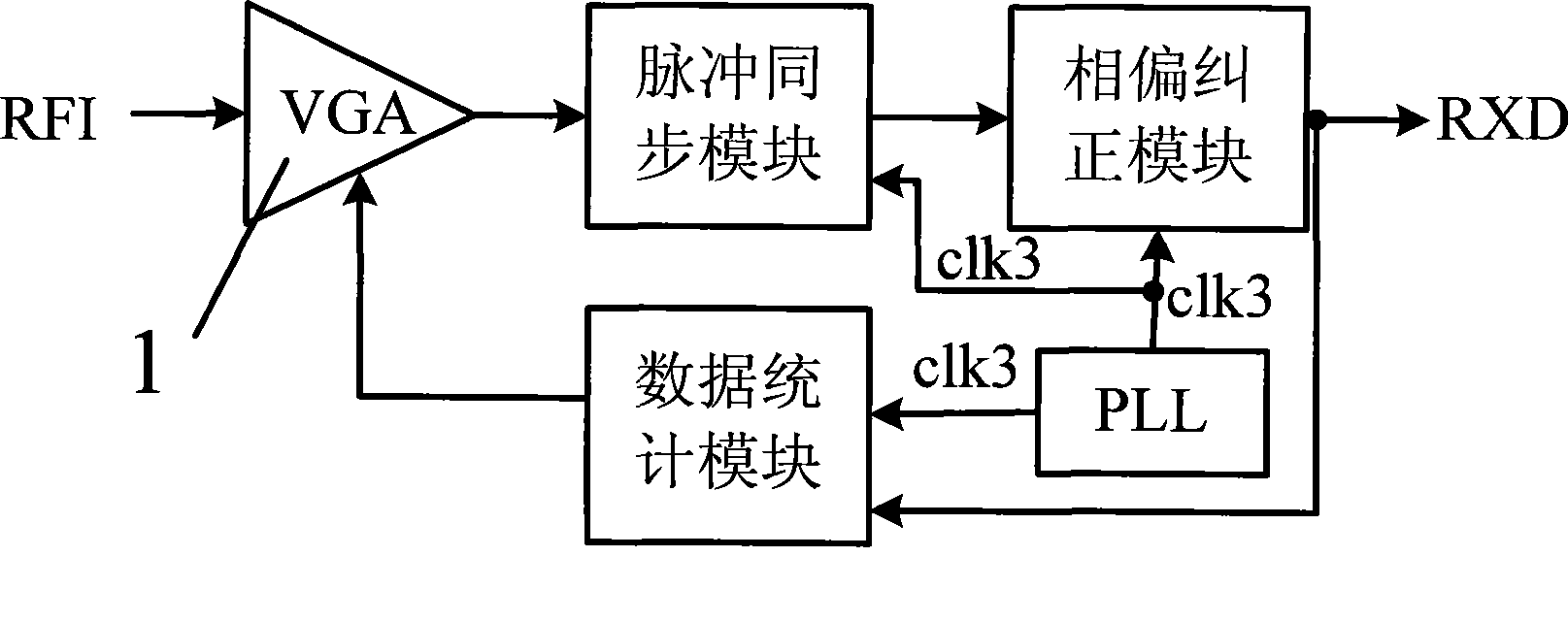
[0027] Such as figure 1 As shown, a pulsed UWB receiver includes a controllable gain amplifier 1 and a trigger receiver 2 connected to each other. The controllable gain amplifier 1 amplifies the received radio frequency signal and outputs it to the trigger receiver 2, and the trigger receiver 2 judges whether the energy of the amplified radio frequency signal exceeds a preset value, and if so, performs asynchronous triggering, Get a high level (that is, data 1), otherwise get a low level (data 0).

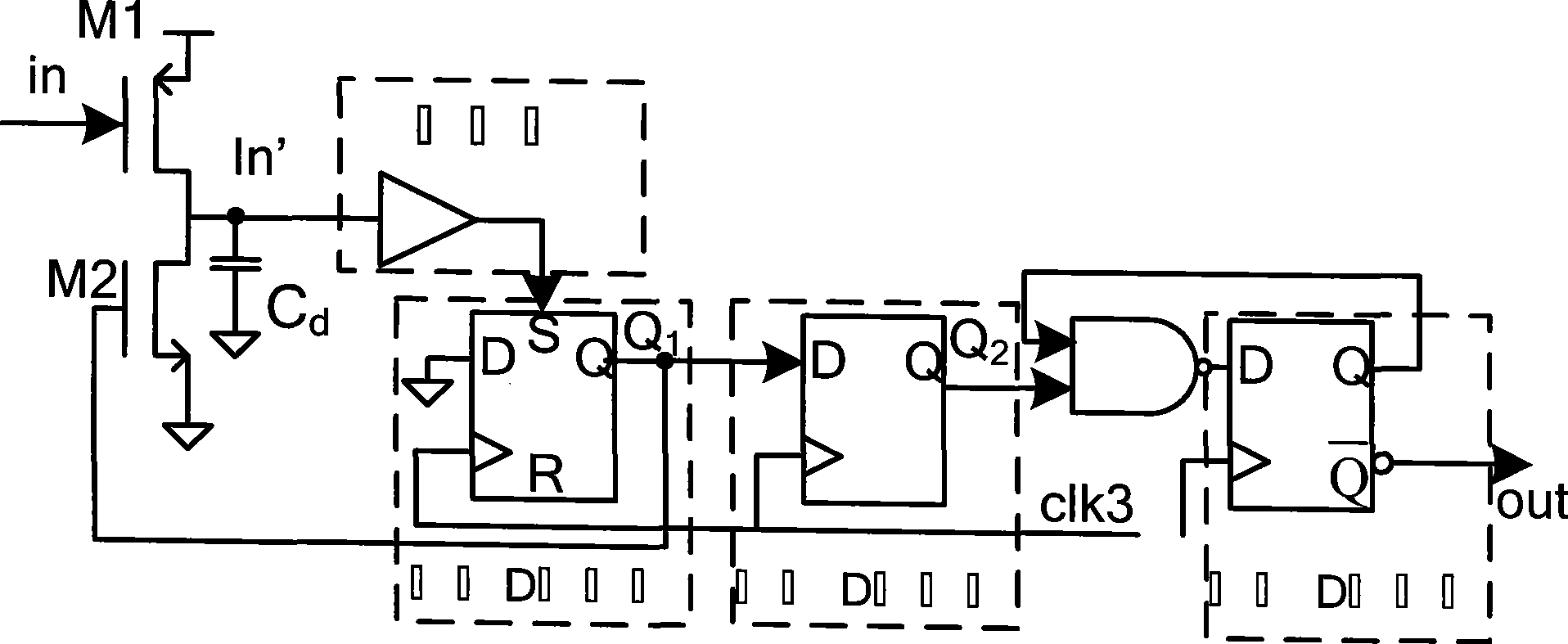
[0028] Such as figure 2 As shown, the trigger receiver includes a pul...


PUM


Abstract

The invention discloses a pulse super-broadband receiver which comprises a controllable gain amplifier and a triggering receiver in mutual connection, wherein the controllable gain amplifier amplifies a received RF signal and outputs the RF signal to the triggering receiver, and the triggering receiver judges whether the energy of the amplified RF signal excesses the preset value, if the energy of the amplified RF signal excesses the preset value, asynchronous triggering is carried out to obtain high electric level, or else, low electric level is obtained. The pulse super-broadband receiver uses a simple digital logic circuit for receiving the super-broadband pulse, avoids the limitations of high power consumption, complex circuits, difficult integration, and the like of the traditional synchronous sampling receiving method in receiving super-broadband signals, has the advantages of simple circuits, easy integration and low power consumption, and is particularly suitable for the super-broadband pulse communication. The invention can correctly receive the signal and greatly reduce the power consumption and the complexity of the receiving circuit, and is helpful for chip realization.

Description

technical field [0001] The invention relates to the fields of wireless communication and integrated circuit design, in particular to a pulse ultra-wideband receiver. Background technique [0002] Ultra-wideband (UWB) technology has attracted people's research interest in recent years because of its unique advantages, and it has a good application prospect in the field of wireless data transmission. [0003] At present, the research on the signal receiving method of the UWB transmission system mainly starts from the communication theory, and mainly follows the method of the traditional narrowband transmission system. The famous Shannon communication theory gives the relationship between the information transmission rate C and resource overhead (signal energy Eb and occupied frequency bandwidth W) in an additive white Gauss noise (AWGN) channel. When people study the signal receiving method, they always try to approach the Shannon limit. The related research of matched filter...

Claims


Application Information

Patent Timeline
IPC IPC(8): H04B1/16H04B1/69H04B1/717
Inventor 江勇胡松华俞小毛
Owner SHENZHEN OUDMON TECH
Learn More