Permanent magnet direct-driving aerogenerator

A wind turbine, permanent magnet direct drive technology, applied in wind turbines, wind turbine combinations, wind power generation, etc., can solve the problem of unsatisfactory failure rate and service life, high production cost of rectifier inverter, complex gearbox structure, etc. problem, to achieve the effect of low noise, simple structure and low production cost

Inactive Publication Date: 2009-05-13
王光顺
View PDF0 Cites 4 Cited by
  • Summary
  • Abstract
  • Description
  • Claims
  • Application Information

AI Technical Summary

Problems solved by technology

Existing wind power generators can be divided into two types: one-pole multi-coil and one-pole-one-coil according to the coil winding form. Among them, the one-pole multi-coil wind power generator requires the rotor to have a higher speed before it can output electric energy. A gearbox is installed between the wind wheel and the generator rotor to increase the speed of the rotor. Due to the complex structure of the gearbox and the large motion load, its service life is short and the failure rate is high; the medium and large wind turbine with one pole and one coil Due to the slow speed, the volume is usually large, the output voltage is a square wave, and there are a large number of high-order harmonics. It needs to be rectified and inverted before it can be connected to the grid. The rectified inverter not only has high production costs, but its failure rate and usage life expectancy is not ideal

Method used


Image

  • Permanent magnet direct-driving aerogenerator
  • Permanent magnet direct-driving aerogenerator
  • Permanent magnet direct-driving aerogenerator

Examples


Embodiment Construction

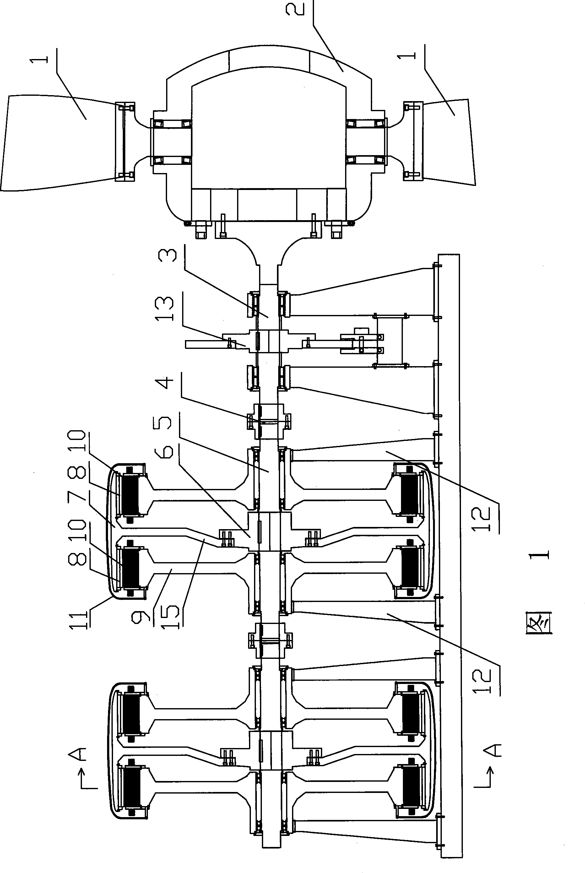
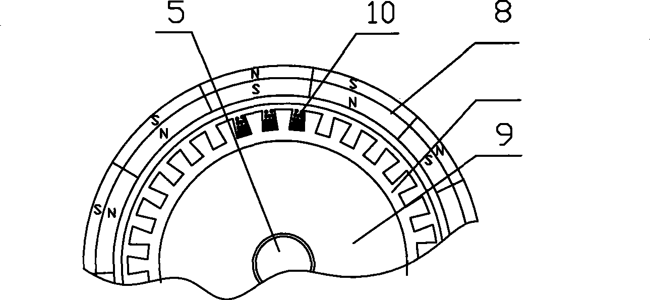
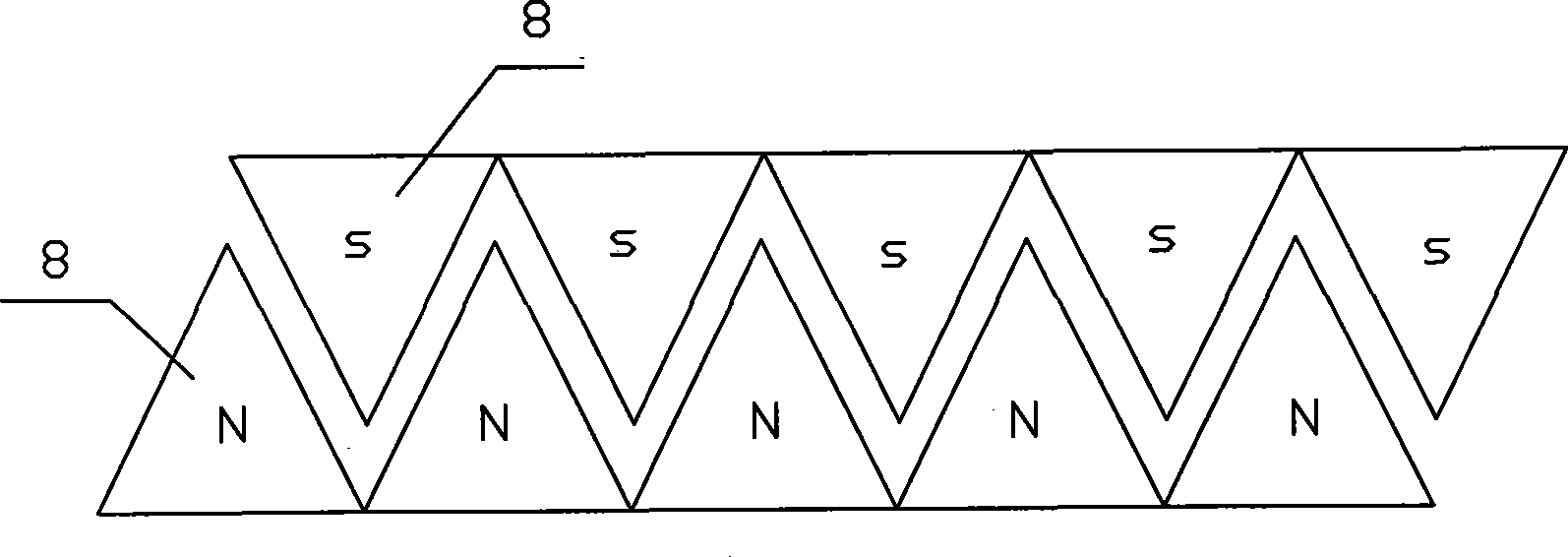
[0021] Fig. 1 is a cross-sectional view of an embodiment of the present invention, in order to express clearly, the section line in the figure is not drawn; As shown in Fig. The wind wheel 2 is installed on the front end of the main shaft 3 . The rear end of the main shaft 3 is connected to the generator shaft 5 through a coupling 4, and the middle section of the generator shaft 5 is fixedly connected with a rotor support 6 through a flat key. The rotor support 6 is disc-shaped, and the generator shaft 5 is vertically inserted in the rotor Center of support 6. The outer ring of the rotor support 6 is fixedly connected to the rotor barrel 7; the rotor barrel 7 is a barrel-shaped part with a rotor frame 15 in the middle, and the rotor frame 15 is a partition arranged horizontally in the barrel cavity, and its center has a The mounting hole of the rotor support 6 is provided with a permanent magnet 8 on the inner wall of the drum cavity on both sides of the rotor frame 15 . The...


PUM


Abstract

The invention relates to a wind power generator, in particular to a permanent magnetic direct driving wind power generator. The wind power generator comprises a wind wheel with an oar blade; and the wind wheel is arranged on the front end of a mainshaft. The mainshaft is connected with a generator shaft through a coupler; the middle section of the generator shaft is fixedly connected with a rotor supporting seat; the outside of the rotor supporting seat is fixedly connected with a rotor barrel; the inner sidewall of the rotor barrel is fixedly connected with a permanent magnet; the generator shaft of two sides of the rotor supporting seat are provided with a coil bracket through a bearing respectively; the outer side of the coil bracket is provided with a stator coil; and the coil bracket is fixedly connected with the supporting seat. The wind power generator ensures the power output at low rotational speed, does not need a gearbox, improves the output efficiency and service life, reduces the fault rate, directly outputs sine alternating current and does not need a rectifying inverter, thereby reducing the fault rate and prolonging the service life; the wind power generator is convenient to realize multistage modularization, has convenient adjustment and low difficulty in transportation and hoisting, can be used for a wind power generator with superlarge power; and parts of the rotors have light quality and the conversion efficiency of electrical energy is high.

Description

technical field [0001] The invention relates to a wind power generator, in particular to a permanent magnet direct drive wind power generator. Background technique [0002] As a clean and renewable energy, wind energy has been paid more and more attention by countries all over the world. Its reserves are huge, and the global wind energy is about 2.74×10 9 MW, of which the available wind energy is 2×10 7 MW is 10 times larger than the total amount of water energy that can be developed and utilized on the earth. China's wind energy reserves are large and widely distributed, and the wind energy reserves on land alone are about 253 million kilowatts. With the development of the global economy, the wind energy market has also developed rapidly. Wind generators use wind energy to drive the blades to drive the main shaft, and when the relative displacement of the stator and rotor occurs, the magnetic field lines are cut and current is generated in the coil. Existing wind power...

Claims


Application Information

Patent Timeline
Patent Type & Authority Applications(China)
IPC IPC(8): F03D9/00F03D1/06F03D1/00H02K7/18H02K1/27H02K1/16F03D9/25
CPCY02E10/725Y02E10/721Y02E10/72
Inventor 邹磊王光顺
Owner 王光顺
Why Eureka
Try Eureka