Thermal recovery circulating system of air compressor

A technology of air compressors and circulation systems, applied in mechanical equipment, machines/engines, liquid variable capacity machinery, etc., can solve problems such as huge equipment installation costs, fuel and electricity costs, and environmental impact

Inactive Publication Date: 2009-05-20
曾德勋
View PDF0 Cites 14 Cited by
  • Summary
  • Abstract
  • Description
  • Claims
  • Application Information

AI Technical Summary

Problems solved by technology

[0003] However, in the above-mentioned prior art, the cooling water tower 2 is used to remove the heat energy generated by the air compressor 1 through heat exchange. The cooling water tower 2 directly discharges the heat into the atmosphere without recycling it, which not only has an impact on the environment (greenhouse effect and environmental

Method used


Image

  • Thermal recovery circulating system of air compressor
  • Thermal recovery circulating system of air compressor

Examples


Embodiment Construction

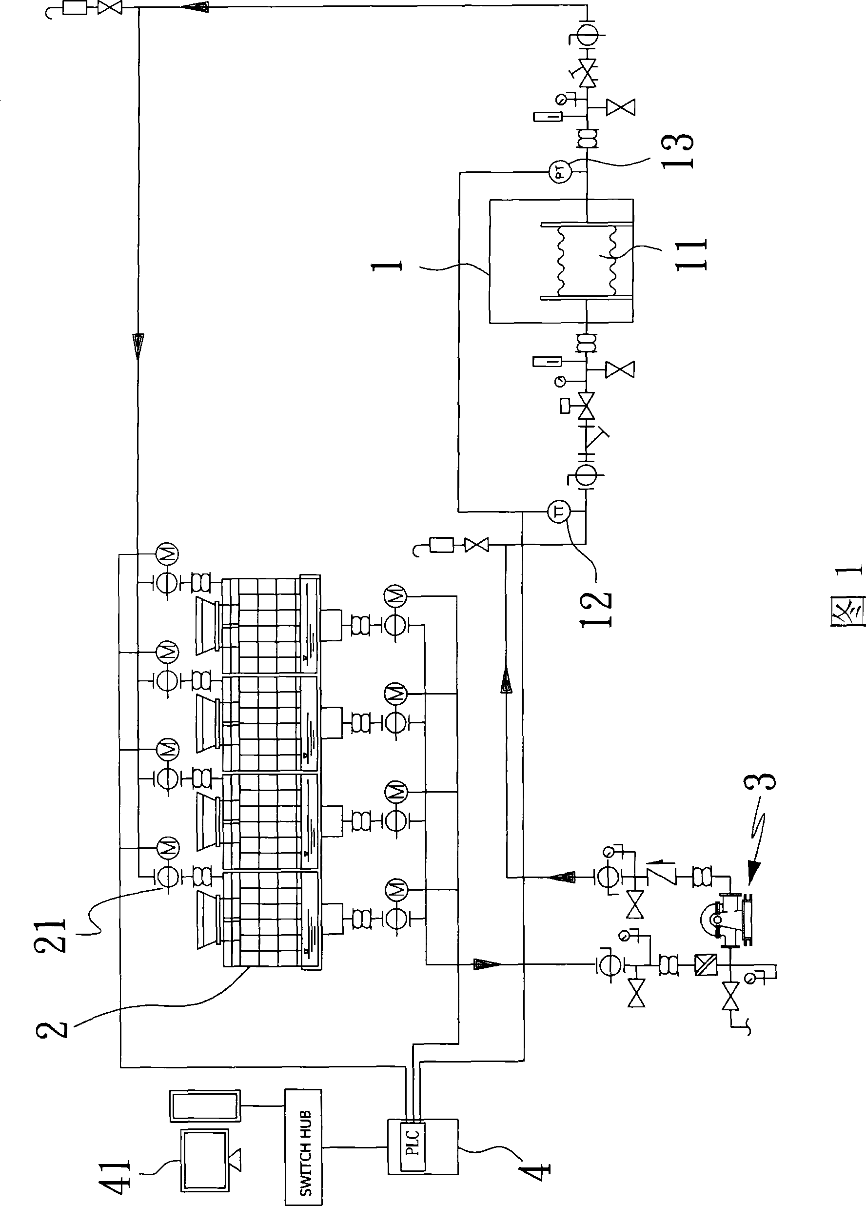
[0015] As shown in FIG. 1 , the air compressor and related cooling device in the prior art, its main components and its missing, have been described above, and will not be repeated here.

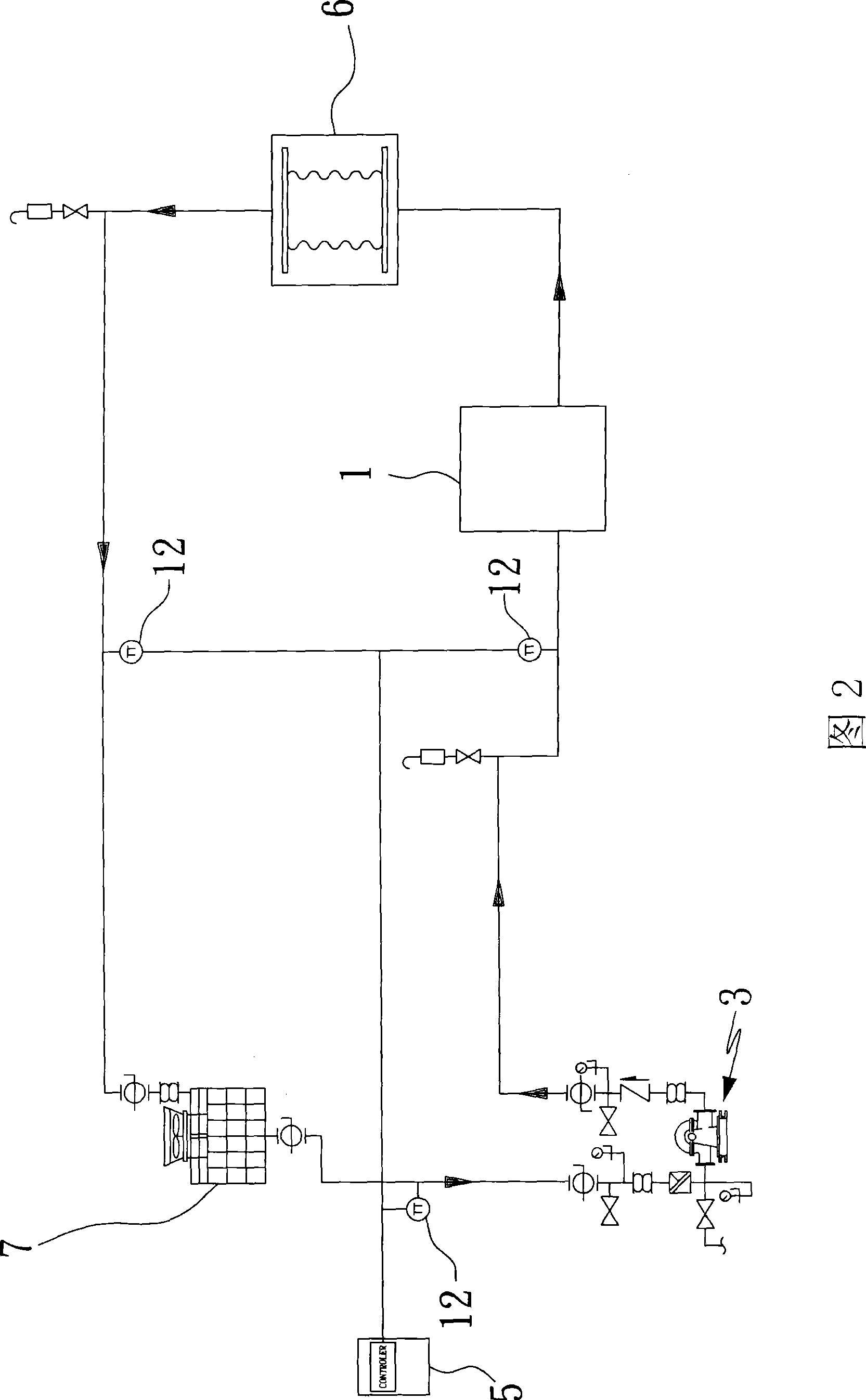
[0016] Fig. 2 is a structural schematic view of an embodiment of the present invention, from which it can be clearly seen that the structure of the embodiment of the present invention mainly includes: an air compressor 1, a cooler 7, a pump 3, a controller 5, and a heat transfer device 6 and other parts, wherein the pump 3 can inject cooling water into the air compressor 1 so as to absorb the heat generated by the air compressor 1 during operation, and then the hotter cooling water passes through the heat transfer device 6 to make the heat transfer device 6 absorb The heat in the cooling water is used to obtain an available heat source and reduce the temperature of the cooling water appropriately. After passing through the heat transfer device 6, the lower temperature cooling water is monitor...


PUM


Abstract

The invention provides a heat recovery and circulating system of an air compressor. Typically, a heat-transferring device is arranged between the air compressor and a cooler. The system can recycle the heat energy produced by the air compressor effectively, and converts the heat into heat resources for other purposes, uses a pump to pressurize cooling water to make the cooling water to pass through the air compressor, the heat transferring device and the cooler respectively, uses a controller to monitor the temperature of the cooling water flowing through the air compressor and the cooler, and then outputs a control signal after calculation according to the preset condition so as to control the acceleration-deceleration or operation stop of the cooler so that the cooling water can flow back to the pump via the cooler after passing through the air compressor and the heat transferring device to form the heat recovery and circulating system. With control of the temperature of the cooling water at control positions, the heat recovery and circulating system can achieve the optimum recovery and heat dissipating efficiency.

Description

technical field [0001] The invention relates to a heat recovery cycle system, in particular to a heat recovery cycle system that can effectively recover heat energy discharged from an air compressor, improve energy use efficiency, and reduce environmental damage caused by carbon dioxide and heat discharge. Background technique [0002] Existing air compressors and related cooling devices, as shown in Figure 1, pump 3 to inject cooling water into the internal cooler 11 of the air compressor 1, after the cooling water absorbs the heat generated by the air compressor 1 during operation Turn into hot water, then flow into the cooling water tower 2 through the control valve 21, use the cooling water tower 2 to cool the hot water into cold water, and then return to the pump 3 to form a cycle; and the above-mentioned cooling water pipeline is in front of the air compressor 1 , the rear end is respectively provided with a temperature transmitter 12, a pressure transmitter 13, can mo...

Claims


Application Information

Patent Timeline
IPC IPC(8): F04B39/06
Inventor 杨文德
Owner 曾德勋
Why Eureka
Try Eureka