
Solution regenerative device of solution dehumidifying air-conditioning system

A solution dehumidification air-conditioning and solution regeneration technology, which is applied in air-conditioning systems, space heating and ventilation, heating methods, etc., can solve the problems of energy utilization grade waste, affecting indoor air quality, etc., and achieve volume and weight reduction, rapid combination, The effect of low temperature

Inactive Publication Date: 2009-05-20
XI AN JIAOTONG UNIV
View PDF4 Cites 30 Cited by
  • Summary
  • Abstract
  • Description
  • Claims
  • Application Information

AI Technical Summary

Problems solved by technology

Cooling requires the temperature of the cooling source to be lower than the dry bulb temperature of the air, and dehumidification requires the temperature of the cooling source to be lower than the dew point temperature of the air. The sensible heat load, which accounts for more than half of the total load, could have been discharged by a high-temperature cooling source, but it is shared with dehumidification at 7°C The low-temperature cold source is processed, resulting in a waste of energy utilization grade
The air is cooled and dehumidified by condensation and dehumidification, the ratio of sensible heat and latent heat absorbed can only change within a certain range, while the heat-humidity ratio required for indoor environment adjustment changes within a large range; moreover, condensation The wet surface produced by the dehumidification method becomes a good place for the reproduction of biological pollutants such as mold, which seriously affects the indoor air quality

Method used

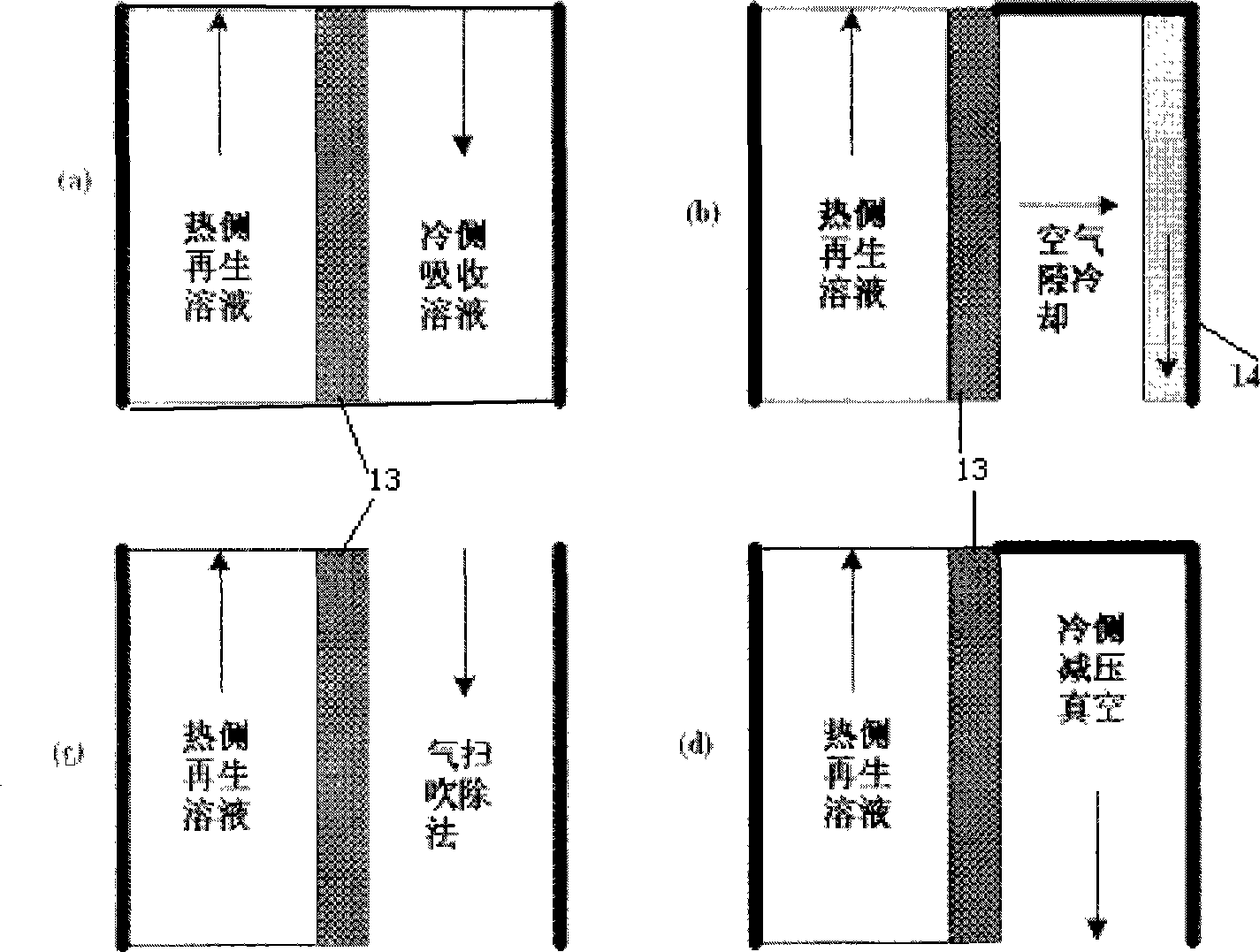
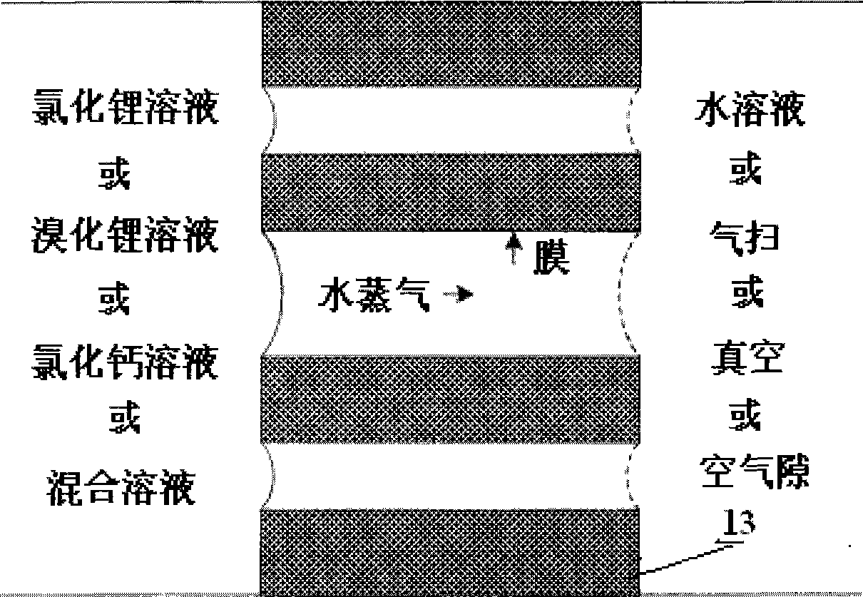

Image

  • Solution regenerative device of solution dehumidifying air-conditioning system
  • Solution regenerative device of solution dehumidifying air-conditioning system
  • Solution regenerative device of solution dehumidifying air-conditioning system

Examples


Embodiment Construction

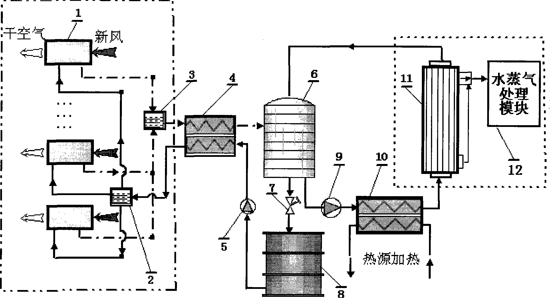
[0022] The structural principle and working principle of the present invention will be further described in detail below in conjunction with the accompanying drawings.

[0023] refer to figure 1 , the structural principle of the present invention is: the outlet of the diluted solution at the bottom of the diluted solution reservoir 6 is connected to the inlet of the regenerative circulating pump 9 through a pipeline, and the outlet of the regenerative circulating pump 9 is connected to the solution inlet of the solution heating device 10 through a pipeline, The solution outlet of the solution heating device 10 is connected to the inlet of the membrane distillation assembly 11, wherein the concentrated solution outlet of the membrane distillation assembly 11 is connected to the upper feed port of the dilute solution reservoir 6, and at the same time, the water vapor outlet of the membrane distillation assembly 11 It is connected with the inlet of the steam processing module 12;...


PUM


Abstract

The invention relates to a solution regeneration unit for a solution dehumidification air-conditioning system based on the membrane distillation technology, which mainly comprises a diluted solution reservoir, a concentrated solution reservoir, a solution heating device, a regenerative circulating pump, a water vapor treatment module and a membrane distillation component. By utilization of the characteristic in the membrane distillation technology that the temperature of driving heat source is low, the heat source temperature required by the solution regeneration process is greatly reduced, and the available temperature difference range of heat energy is increased; meanwhile, by utilization of the large contact area provided by a membrane component under unit volume and the expandability of the membrane component, the volume and the weight of a solution regeneration system are greatly reduced. Compared with the prior packed tower solution regeneration unit, the solution regeneration unit has low operating temperature and the heat energy during the operating process is only used for transmembrane latent heat transfer of water vapor, so that the energy consumption is small.

Description

technical field [0001] The invention belongs to the fields of air conditioning, application of membrane distillation technology, and utilization of low-grade renewable energy, and relates to humidity control in air conditioning and a solution concentration and separation device in membrane distillation technology, in particular to a solution regeneration device for a solution dehumidification air conditioning system. Background technique [0002] Indoor temperature and humidity control is the main task of the air conditioning system. At present, common air-conditioning systems control temperature and humidity by sending treated air into the room and relying on heat and mass exchange with the indoor air. The air conditioning system generally adopts the condensation dehumidification method, using 7 ℃ cold water to realize the cooling and dehumidification of the air, and at the same time remove the sensible heat load and latent heat load of the conditioning space. Cooling requ...

Claims


Application Information

Patent Timeline
IPC IPC(8): F24F3/14B01D53/26B01D61/36
Inventor 顾兆林王赞社冯诗愚李云
Owner XI AN JIAOTONG UNIV
Learn More