Tail fiber coupling output device of laser diode array / surface array

A laser diode, coupling-out technology, applied in the coupling of optical waveguides, lasers, laser parts and other directions, can solve the problems of difficult adjustment, complex optical shaping devices, and high production costs, and achieve simplified process, huge economic potential, principle and Simple and easy process

Inactive Publication Date: 2009-05-20
BEIJING JIAOTONG UNIV
View PDF6 Cites 16 Cited by
  • Summary
  • Abstract
  • Description
  • Claims
  • Application Information

AI Technical Summary

Problems solved by technology

[0005] Or use prisms and mirrors to split, rotate and rearrange the output beams of laser diode arrays and area arrays to achieve a balanced beam quality on the fast and slow axes to facilitate further focusing and coupling into pigtails. For such technologies, see [Chinese patent application No.: 0510011495.9 A method of folding anti-prism stacks to realize bar array semiconductor laser shaping, Chinese patent application number: 0510011241.7 A method for realizing beam shaping of semiconductor lasers by a coaxial symmetric microreflector array, Chinese patent application number: 0710063249.7 Realizing high-power laser diode stack beams Shaping device and Chinese patent application number: 0710056218.9 A beam shaping device for an area array semiconductor laser], the disadvantage of this type of method is that the optical shaping device is very fine and complex, not only the production cost is high but also difficult to adjust

Method used


Image

  • Tail fiber coupling output device of laser diode array / surface array
  • Tail fiber coupling output device of laser diode array / surface array
  • Tail fiber coupling output device of laser diode array / surface array

Examples


Embodiment 1

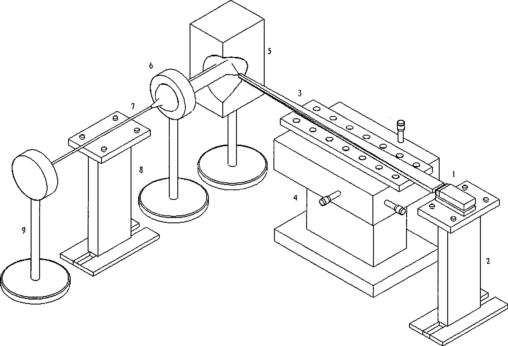
[0025] A pigtail fiber coupling output device with fast axis collimation laser diode array, see figure 1 . The devices used in this device are: laser diode array 1 with fast axis collimation; laser platform support 2; optical fiber taper 3 with long input end face; precision three-dimensional adjustment platform 4; the first parabolic reflector The parameter of 5 is p=4; the curvature radius of the first spherical focusing lens 6 is 3 mm, the single-mode optical fiber 7 , and the optical fiber fixing bracket 8 .

[0026] The connection between the above devices constituting the device: the light-emitting surface of the laser diode array 1 with fast axis collimation is close to the input end face of the optical fiber tapered body 3 whose input end face is elongated; the input end face is elongated optical fiber The end of cone 3 is positioned at the focal point of first parabolic mirror 5; The light beam collimated by the parabolic reflector 5 is focused; the single-mode fibe...

Embodiment 2

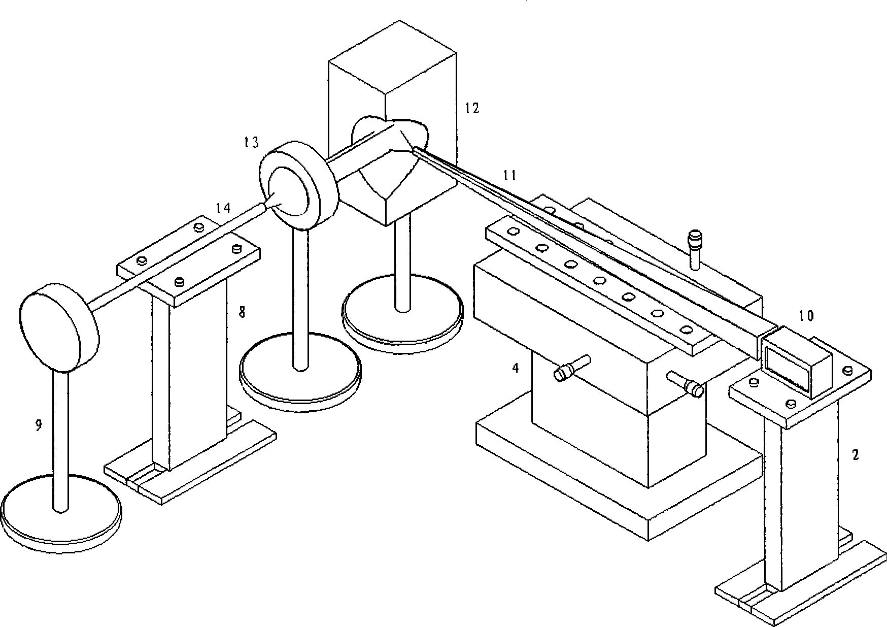
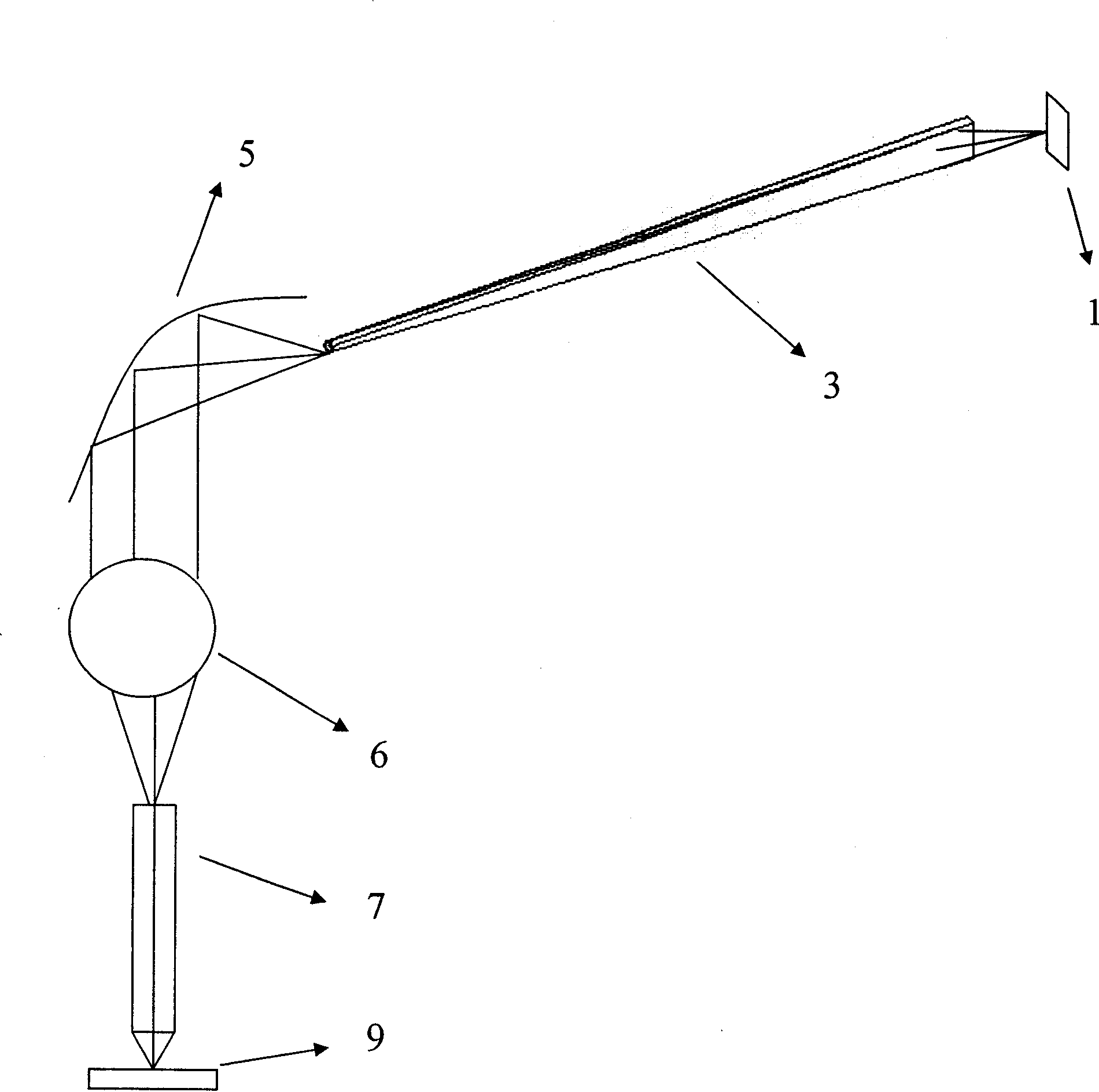
[0032] A pigtail fiber coupling output device with fast axis collimated laser diode area array, see figure 2 , 5 . The devices used in this device are: a laser diode array 10 with fast axis collimation, a laser platform support 2, an optical fiber cone 11 with a square input end face, a precision three-dimensional adjustment platform 4, and a second parabolic reflector 12. The parameter p=8, the radius of curvature of the second spherical focusing lens 13 is 6 mm, the diameter of the double-clad optical fiber 14 is 300 um, and the optical fiber fixing bracket 8 .

[0033] The optical fiber tapered body 11 with a square input end face uses an optical fiber drawing tower to carry out reverse drawing processing on a square optical fiber preform with a side length of 14mm in cross section. Rod uniformly reduced to a bare fiber with a diameter of 400um and a total length of 30cm ( figure 2 , 5 ), the diameter change is linearly proportional to the length of the optical fiber ...


PUM


Abstract

The invention discloses a tail fiber coupling output device of a laser diode array / area array, relates to beam shaping and coupling of a semiconductor laser, and is used for manufacturing a high-efficiency high-power tail fiber output laser diode array / area array. A luminous surface of the laser diode array or area array with fast axis collimation is closely attached with a rectangular or square input end surface of an optical fiber cone; the tail end of the optical fiber cone with the rectangular or square input end surface is positioned on the focus of a first parabolic reflector or the focus of a second parabolic reflector; the first parabolic reflector or the second parabolic reflector are arranged on the focus on one side of a first spherical focusing lens or a second spherical focusing lens respectively; and a single mode optical fiber or a double-coated optical fiber is respectively positioned on the focus on the other side of the first spherical focusing lens or the second spherical focusing lens.

Description

technical field [0001] The invention belongs to the technical field of beam shaping and coupling of semiconductor lasers. It can be used to manufacture laser diode arrays or area arrays with high-efficiency and high-power pigtail output. Background technique [0002] High-power double-clad fiber lasers and amplifiers have vital applications in national defense, industrial advanced laser manufacturing, precision welding, and laser radar. The pumping sources of such high-power double-clad fiber lasers and amplifiers are generally laser diode arrays and area arrays. Therefore, how to efficiently couple the pump light of the laser diode array and the area array into the double-clad fiber has become the technical key to the production of high-power fiber lasers and amplifiers. [0003] As the core technology of high-power fiber lasers and amplifiers, pump coupling technology aims to couple the pump light power of laser diode arrays and area arrays with hundreds of watts or even...

Claims


Application Information

Patent Timeline
Patent Type & Authority Applications(China)
IPC IPC(8): G02B27/09G02B6/32G02B6/42H01S5/00
Inventor 张帆刘楚王春灿耿蕊陆玉春刘鹏
Owner BEIJING JIAOTONG UNIV
Why Eureka
Try Eureka