
Super-deep well wireless transmission well testing system

A wireless transmission, ultra-deep well technology, applied in the direction of wellbore/well components, measurement, earthwork drilling and production, etc., can solve the problems of easy waste of time, long recovery time, long pressure recovery time, etc., to achieve simple operation and maintenance, The effect of improving accuracy and completeness and shortening construction work time

Active Publication Date: 2013-06-12
XINJIANG SINOGASOLINEEUM ENG
View PDF0 Cites 1 Cited by
  • Summary
  • Abstract
  • Description
  • Claims
  • Application Information

AI Technical Summary

Problems solved by technology

Due to the existence of the wellbore storage effect, the pressure recovery time is longer, and sometimes the pressure recovery test cannot obtain qualified data due to the wellbore storage effect
[0004] At present, there is a direct-reading method. The direct-reading pressure gauge is first lowered to the bottom of the well with a cable, and then the well is closed on the ground. After the bottom-hole pressure is restored, the required data can be read on the ground immediately. Well, it takes a long time to wait for the downhole pressure to recover, and the direct-reading pressure gauge needs cable connection, and the cable will have a certain impact on the shut-in equipment during well shut-in
[0005] The other way is to use the storage type pressure gauge, lower the pressure gauge to the predetermined position with the pipe string, then close the oil well, take it out from the downhole after a certain period of time, and then read the stored equipment. The recovery of the pressure in the well cannot be known exactly whether the well is shut in on the surface or in the downhole. Instead, it depends on the experience of the operator to judge when the downhole pressure will recover. There is a large deviation in the measurement results obtained, and the entire test time cannot be grasped, and it is easy to waste a lot of time
[0006] The oil well test equipment currently used cannot complete the test of ultra-deep wells, and can only be used in oil wells with a depth of about 2000-3000 meters in some plain areas, and cannot achieve measurement results in oil well tests in Northwest China

Method used


Image

  • Super-deep well wireless transmission well testing system
  • Super-deep well wireless transmission well testing system
  • Super-deep well wireless transmission well testing system

Examples


Embodiment Construction

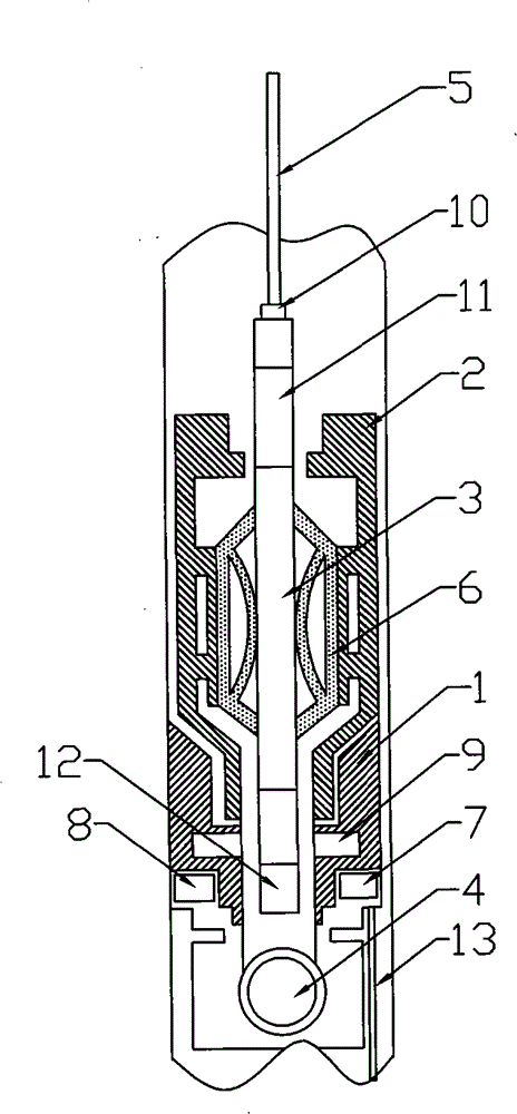
[0026] Such as figure 1 As shown, the test system of this scheme is composed of three parts: downhole equipment, cable 5 and ground equipment. Analyze various data to draw conclusions about the underground situation.

[0027] The downhole equipment includes: support tube 1, positioning joint 2, direct reading pressure gauge 7, receiver 12, battery 6, storage electronic pressure gauge 9, etc. Multiple grooves 15 are opened on the outer wall of the support tube depending on the situation. There are four grooves 15 on the outer wall of the cylinder 1, in which the direct-reading pressure gauge 7, the battery 8, and optionally one or two storage pressure gauges 9 are installed, and a pressure transmission channel is opened in the tube wall of the cylinder 1 13 Transmit the pressure under the test valve test valve 4 to the direct-reading pressure gauge 7 or / and storage pressure gauge 9, inside the direct-reading pressure gauge 7 are installed sensors, A / D modules, microcontrollers...


PUM


Abstract

The invention discloses a wireless transmission well testing system of an ultra-deep well and relates to the filed of dynamic monitoring of an oil reservoir, in particular to a device for a pressure buildup test for an oil gas production well. The proposal utilizes a ground receiving device, a cable, a supporting cylinder, a sensing system and a ball valve; the supporting cylinder is connected with the upper part of the ball valve; the outer wall of the supporting cylinder is provided with a groove; the inside of a tube is provided with a pressure transmission passage from the lower part of the ball valve to a groove of a direct-reading manometer; the sensing system comprises the direct-reading type manometer, a cell and a receiver; the direct-reading type manometer and the cell are arranged inside the groove of the outer wall of the supporting cylinder respectively; the direct-reading type manometer consists of a sensor, an A / D module, a microcontroller, a signal emitter and a transmitting coil which are sequentially connected; the receiver consists of a receiving coil, a signal receiver, a microcontroller and a signal transmitter which are sequentially connected; and the receiver is arranged inside the supporting cylinder and is connected with the ground receiving device through the cable. The proposal realizes well shutdown underground, avoids accumulation in a well cylinder, shortens the well testing period, can fully avoid causing incomplete underground pressure buildup curve by insufficient time for well shutdown, can set sampling density at any moment through a ground computer, avoids causing the loss of wire section in early stage and meets the testing requirement of well testing of the oil gas well.

Description

technical field [0001] The invention relates to the field of oil reservoir dynamic monitoring, in particular to a device for pressure recovery testing of oil and gas production wells. Background technique [0002] The pressure recovery test can obtain formation parameters such as static pressure, flow pressure, permeability, flow coefficient, skin coefficient (wellbore contamination), reservoir boundary and distance, production pressure difference, etc. Provide reliable basis; pressure recovery test data is not only an important basis for oil well stimulation measures such as water injection, acidification, plug removal, profile control, etc., but also the main means to test the effect of oil well measures. [0003] The conventional pressure recovery test of the production well is to lower the pressure gauge to the middle of the oil layer to measure the flow pressure when the oil well is in normal production, and then shut down the well on the ground. Since there is a large ...

Claims


Application Information

Patent Timeline
Patent Type & Authority Patents(China)
IPC IPC(8): E21B47/12E21B49/00E21B47/06
Inventor 杨晓辉张福祥彭建新赵峰蔡进王宁李志国朱进府庞怀庆
Owner XINJIANG SINOGASOLINEEUM ENG
Learn More