Method for detecting residual stress of steel by X-ray

A residual stress and X-ray technology, applied in the field of residual stress determination by X-ray diffraction, can solve the problems of reduced application efficiency, weakened corrosion peeling, limited penetration depth, etc., to improve the measurement accuracy, easy to control the corrosion rate, regular strong effect

Inactive Publication Date: 2009-06-10
CHONGQING UNIV
View PDF0 Cites 20 Cited by
  • Summary
  • Abstract
  • Description
  • Claims
  • Application Information

AI Technical Summary

Problems solved by technology

However, due to the limited penetration depth of X-rays to steel, usually only a few microns deep, for example, the penetration depth of CrKa to steel plates is about 1-10 μm, which greatly limits the application of this method in thicker components.
Although the neutron diffraction method can better solve this problem, it is impossible to apply it to the actual detection because this method needs to build a nuclear reactor to collect neutrons.
[0005] For large-thickness steel structure workpieces, there is also a method of combining electrolytic corrosion peeling and mechanical processing, that is, after turning the surface of the component, the stress-affected layer of machining is stripped by electrolytic corrosion. This method Although a large-area smooth plane can be obtained as a test surface, as far as the method is concerned, the advantage of the corrosion and peeling method that no residual stress will be introduced has been greatly weakened, and the determination of the depth of the stress-affected layer itself is a complicated process.
First determine the depth of the impact layer and then peel off the impact layer before measuring, this process greatly reduces its practical application efficiency
At the same time, in practical applications, due to the limitation of size and shape of some large structural parts, it is unrealistic to turn first and then corrode.

Method used


Image

  • Method for detecting residual stress of steel by X-ray
  • Method for detecting residual stress of steel by X-ray
  • Method for detecting residual stress of steel by X-ray

Examples


Embodiment Construction

[0024] The method of measuring the residual stress of steel by X-ray has the following steps:

[0025] (1) Electrolytic corrosion

[0026] Take the galvanized sheet and polish the smooth surface;

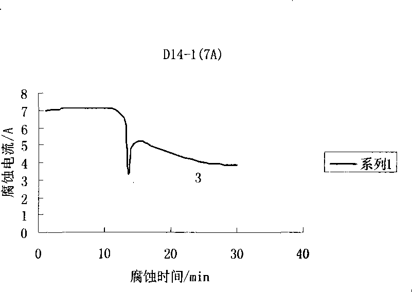
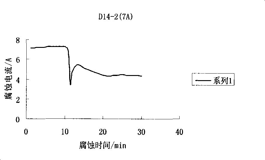
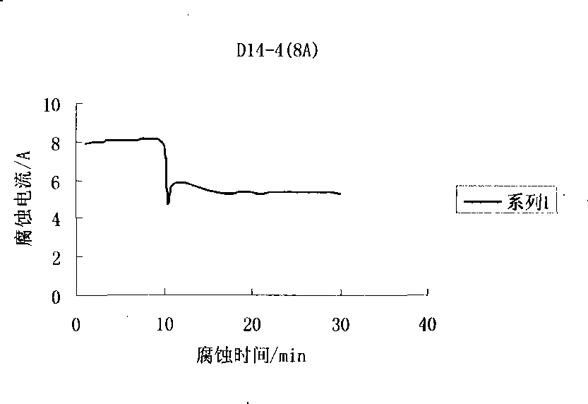
[0027] Saturated NaCl aqueous solution is the electrolyte, the component to be tested is used as the anode corrosion end, galvanized iron sheet is used as the cathode, DC constant voltage corrosion, the electrolytic corrosion time is set according to the required corrosion area and depth of the component, and the corrosion current is 7-8A;

[0028] (2) After corrosion and peeling, use an X-ray stress meter to measure the residual stress in the vertical direction of the weld, and then use the method of single-sided peeling to measure the stress value correction method to correct the measured value of the residual stress after peeling, that is, the steel Residual Stress.

[0029] The present invention takes the weldment of 921A steel plate as an example to carry out the electrochemi...


PUM


Abstract

The invention relates to a method of mensurating steel residual stress using X rays, comprising: (1) taking a galvanized sheet, polishing smooth surface layers; taking saturated NaCl aqueous solution as electrolyte, using measured components as anode corrosion ends, using galvanized sheet iron as a cathode, eroding by DC constant pressure, corrosion current being 7-8 A; (2) after corrosion cleavage, mensurating residual stress on vertical direction of welding using X rays, then correcting residual stress measurement value after cleavage using single side cleavage measurement stress value correction method, namely obtaining steel residual stress. According to the inventive method to measurate the steel residual stress, novel additional stress is not increased by electrolytic corrosion cleavage, also measurement result along heavy gauge workpieces is obtained, measurement result is simple, device cost is low.

Description

technical field [0001] In particular, the invention relates to a method for determining residual stress by X-ray diffraction. Background technique [0002] The instantaneous high temperature and rapid cooling generated during the steel welding process will be accompanied by the phase change of the steel, causing the steel to expand and contract. The steel in the weld pool and the heat-affected zone cannot be freely deformed due to the constraints of adjacent steel. High thermal stress and phase transformation stress are generated in the workpiece. In some weldments, where the residual stress is high, such as at the welding angle, the stress value may reach or exceed the yield strength of the steel, and at this time the steel will undergo plastic deformation, that is, welding deformation. The resulting welding deformation will directly affect the dimensional accuracy, bearing capacity, safety and stability of the weldment, so it is necessary to detect the distribution of res...

Claims


Application Information

Patent Timeline
Patent Type & Authority Applications(China)
IPC IPC(8): G01N23/20
Inventor 陈玉安李德成程绩胡玲周飞旭
Owner CHONGQING UNIV
Why Eureka
Try Eureka