Plasma body fuel cell

A plasma and fuel cell technology, applied in fuel cells, solid electrolyte fuel cells, fuel cell additives, etc., can solve the problems of unrecoverable fuel residual gas and impracticality

Inactive Publication Date: 2009-06-10
肖远科 +1
View PDF2 Cites 25 Cited by
  • Summary
  • Abstract
  • Description
  • Claims
  • Application Information

AI Technical Summary

Problems solved by technology

When the system is working, the plasma discharge itself requires more than 8 kilowatts of power. Therefore, the system must produce an output power greater than 8 kilowatts for its efficiency to have practical significance, and its output current will reach more t

Method used


Image

  • Plasma body fuel cell
  • Plasma body fuel cell
  • Plasma body fuel cell

Examples


Embodiment Construction

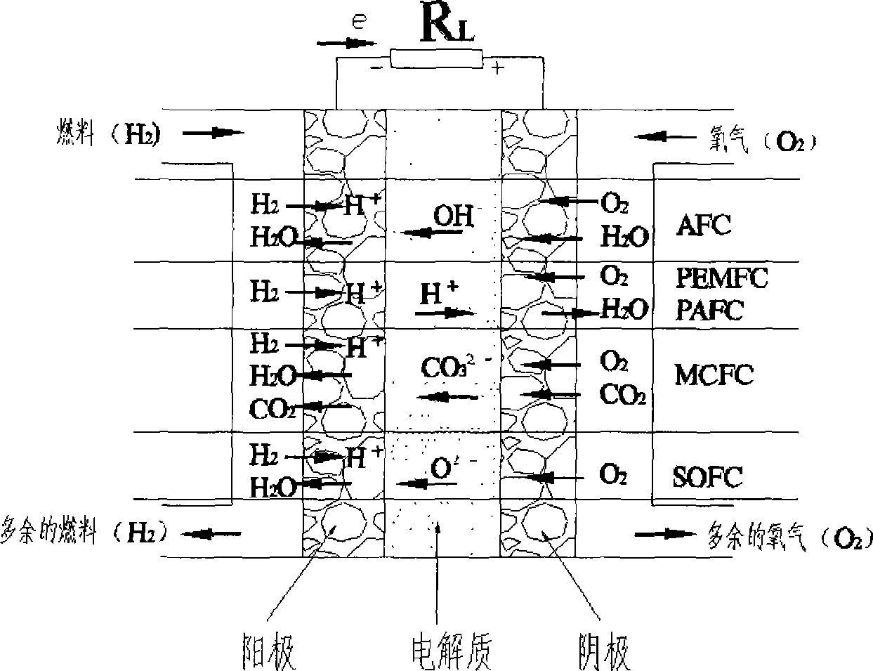
[0075] figure 1 Shown are currently reported, including alkaline fuel cell (AFC), phosphoric acid fuel cell (PAFC), molten carbonate fuel cell (MCFC), solid oxide fuel cell (SOFC), proton exchange membrane fuel cell The basic working principles of fuel cells such as (PEMFC) are as mentioned above.

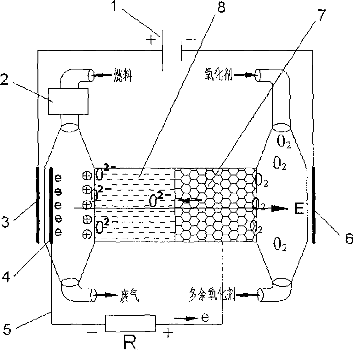
[0076] figure 2 It is the structural principle of the plasma fuel cell of the present invention. The plasma jet flow generation unit 2 that is equipped with a pressurized blowing mechanism such as the air plasma cutting machine commonly used at present is used as the plasma source for making the fuel gas into plasma, and in the direction of the running path of the plasma flow ejected by it. A plasma separation field in the form of an applied electric field or magnetic field (shown in the figure as an electrostatic separation field) is provided with a field force direction perpendicular to its running direction. In the direction of movement of the positive and negative ions sepa...


PUM


Abstract

The invention provides a plasma fuel cell. An additional ion separation field with field direction which is vertical to running direction is arranged on a plasma flow operating path after a plasma jet generation unit; and corresponding collection structures are arranged on moving directions of separated cation and anion, wherein an electron collection structure is connected with an electric energy output circuit of an electron transfer circuit which is used for moving collected electrons out of the separation field; the electrons are transferred to a porous electrode structure which is on anion collecting side, is communicated with an oxygen introducing structure, and is isolated from the anions by a solid oxide electrolysis isolation structure; oxygen anions reduced by the electrons are combined with cations collected via isolation through the solid oxide electrolysis isolation structure to release converted electric energy to the outside. The cell can break electrostatic balance with feasibility, has a simple structure, can use various fuel gases and effectively recover fuel residual gas, does not need a noble metal catalyst or a biopolar plate so as to reduce the cost, and has the advantages of fast starting, large power and good loading adaptability.

Description

technical field [0001] The invention relates to a fuel cell, in particular to a fuel cell in which fuel gas undergoes plasma transformation and participates in an electrochemical reaction process to convert chemical energy into electrical energy and output the fuel gas to an external load. Background technique [0002] The essence of a fuel cell is to directly convert the chemical energy in a fuel compound into electrical energy through an electrochemical reaction in an appropriate manner, that is, to convert a fuel compound with a higher chemical energy state into a relatively lower chemical energy state. Binding bonds (such as H 2 O.CO 2 etc.) compounds, a device that converts the released chemical potential energy directly into electrical energy capable of outputting work to an external load, rather than releasing it in the traditional way of light and heat (Xu Shisen, Cheng Jian: "Fuel Cell Power Generation System", China Electric Power Publishing House, 2006.1 first e...

Claims


Application Information

Patent Timeline
IPC IPC(8): H01M8/10H01M8/04H01M8/02H01M8/06
CPCY02E60/521Y02E60/50Y02P70/50
Inventor 肖远科
Owner 肖远科
Why Eureka
Try Eureka