Hydrocarbon oil conversion method

A hydrocarbon oil and catalyst technology, applied in chemical instruments and methods, cracking, inorganic chemistry, etc., can solve the problem of low hydrogen production rate and achieve the effect of increasing hydrogen production rate

Active Publication Date: 2009-06-17
CHINA PETROLEUM & CHEM CORP +1
View PDF1 Cites 3 Cited by
  • Summary
  • Abstract
  • Description
  • Claims
  • Application Information

AI Technical Summary

Problems solved by technology

[0005] The purpose of the present invention is to provide a method for hydrocarbon oil conversion that can improve the hydrogen yield in order to overcome the low hydrogen production rate of the existing hydrocarbon oil conversion method

Method used


Image

  • Hydrocarbon oil conversion method
  • Hydrocarbon oil conversion method

Examples


Embodiment 1

[0040] This example is used to illustrate the hydrocarbon oil conversion method provided by the present invention.

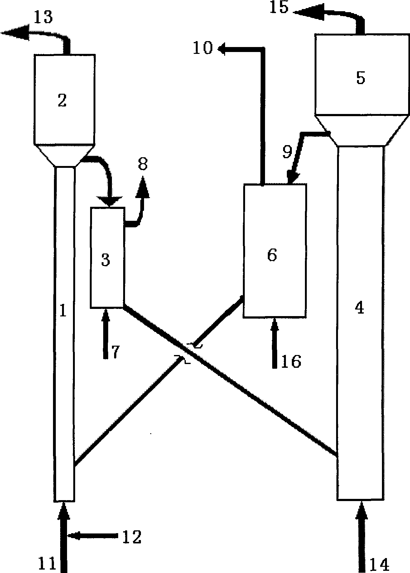
[0041] Such as figure 1 As shown, the regenerated catalyst completely regenerated in the second regenerator 6 is sent to the bottom of the riser reactor 1, hydrocarbon oil 11 and steam 12 are added from the bottom of the riser reactor 1, and the catalyst is contacted with the hydrocarbon oil to obtain Reaction products and spent catalysts. The reaction conditions in the riser reactor 1 include: the reaction temperature is 480°C, the reaction time is 3 seconds, the weight ratio of catalyst to hydrocarbon oil is 5:1, the reaction pressure is 200 kPa, the weight ratio of water vapor to hydrocarbon oil is It is 0.08:1.

[0042] The reaction product 13 and the raw catalyst are separated by the settler 2, and then the raw catalyst is stripped by the stripper 3 and sent to the first regenerator 4, and the oxygen-containing gas 14 is added from the bottom of the first...

Embodiment 2

[0048] This example is used to illustrate the hydrocarbon oil conversion method provided by the present invention.

[0049] The hydrocarbon oil is converted according to the same method as in Example 1. The difference is that the reaction conditions in the first regenerator include: the reaction temperature is 600 ° C, the reaction bed is a fluidized bed, and the empty bed gas velocity is 1 m / seconds, the reaction time is 10 seconds, and the bed pressure is 200 kPa; the oxygen-containing gas is a mixture of oxygen and water vapor, and the oxygen is 15% by volume of the total amount of the mixture; 8% by weight of catalyst. The composition of the synthesis gas is shown in Table 3.

Embodiment 3

[0054] This example is used to illustrate the hydrocarbon oil conversion method provided by the present invention.

[0055] The hydrocarbon oil is converted according to the same method as in Example 1. The difference is that the reaction conditions in the first regenerator include: the reaction temperature is 700 ° C, the reaction bed is a fluidized bed, and the empty bed gas velocity is 1.2 m / seconds, the reaction time is 15 seconds, and the bed pressure is 300 kPa; the oxygen-containing gas is a mixture of oxygen and water vapor, and the oxygen is 25% by volume of the total amount of the mixture; 12% by weight of catalyst. The composition of the synthesis gas is shown in Table 3.


PUM

PropertyMeasurementUnit
particle diameteraaaaaaaaaa
particle sizeaaaaaaaaaa

Abstract

The present invention discloses a hydrocarbon oil convert method, wherein the method includes the following procedures: under cracking condition, contact hydrocarbon oil with energizing agent in a reactor to obtain reaction product and spent catalyst; separate the reaction product and spent catalyst, contact the spent catalyst with oxygen-containing gas in a first regenerator to obtain forming gas and semi- regenerated catalyst; separate the forming gas and the semi- regenerated catalyst, and the semi- regenerated catalyst regenerates in a second regenerator and the regenerated catalyst can be used for periodic duty, wherein the spent catalyst contacts with the oxygen-containing gas with a accessory ingredient exists, and the accessory ingredient contains heat resisting inorganic oxidate carrier and active ingredient that loaded on the carrier and can adsorb carbonic anhydride; the accessory ingredient desorbs carbonic anhydride in the second regenerator and desorbed accessory ingredient can be used for periodic duty. The hydrocarbon oil convert method provided in the invention can improve hydrogen rate of production while heavy crude hydrocarbon lightweight.

Description

technical field [0001] The invention relates to a hydrocarbon oil conversion method. Background technique [0002] Catalytic cracking is one of the important means of petroleum secondary processing, which is used to produce gasoline, diesel, liquefied petroleum gas, etc. from heavy hydrocarbon oil. Generally speaking, the hydrocarbon oil cracking method includes contacting the hydrocarbon oil with a catalyst in a reactor under cracking conditions, and the hydrocarbon oil generates cracked products (the cracked products include light oil and gas) through a cracking reaction under the action of the catalyst. At the same time, the coke generated by the reaction is deposited on the catalyst, and the catalyst deposited with coke is generally called the spent catalyst; the spent catalyst and the cracked product are separated in the reaction settler, and the spent catalyst enters the reaction stripper to remove the carried oil gas After entering the regenerator for regeneration, t...

Claims


Application Information

Patent Timeline
Patent Type & Authority Applications(China)
IPC IPC(8): C10G11/20C01B3/26
CPCY02P20/584Y02P30/40
Inventor 龙军吴治国汪燮卿张久顺毛安国谢朝钢
Owner CHINA PETROLEUM & CHEM CORP
Why Eureka
Try Eureka