Oil-containing alkali liquor separation apparatus and method

A separation device and separation method technology, applied in separation methods, liquid separation, chemical instruments and methods, etc., can solve the problems of many by-products, complex processes, heavy environmental pollution, etc., and achieve low disulfide content, reasonable and practical process. , good separation effect

Active Publication Date: 2009-07-01
NINGBO ZHONGYI PETROCHEM TECH
View PDF6 Cites 19 Cited by
  • Summary
  • Abstract
  • Description
  • Claims
  • Application Information

AI Technical Summary

Problems solved by technology

[0020] CN96115789.5 discloses a method for preparing methanesulfonic acid, which uses dimethyl disulfide and hydrogen peroxide as raw materials, and under the action of a catalyst, undergoes an oxidation reaction, which is purified, evaporated and concentrated, and mainly solves the problem of exis

Method used


Image

  • Oil-containing alkali liquor separation apparatus and method
  • Oil-containing alkali liquor separation apparatus and method
  • Oil-containing alkali liquor separation apparatus and method

Examples


example 1

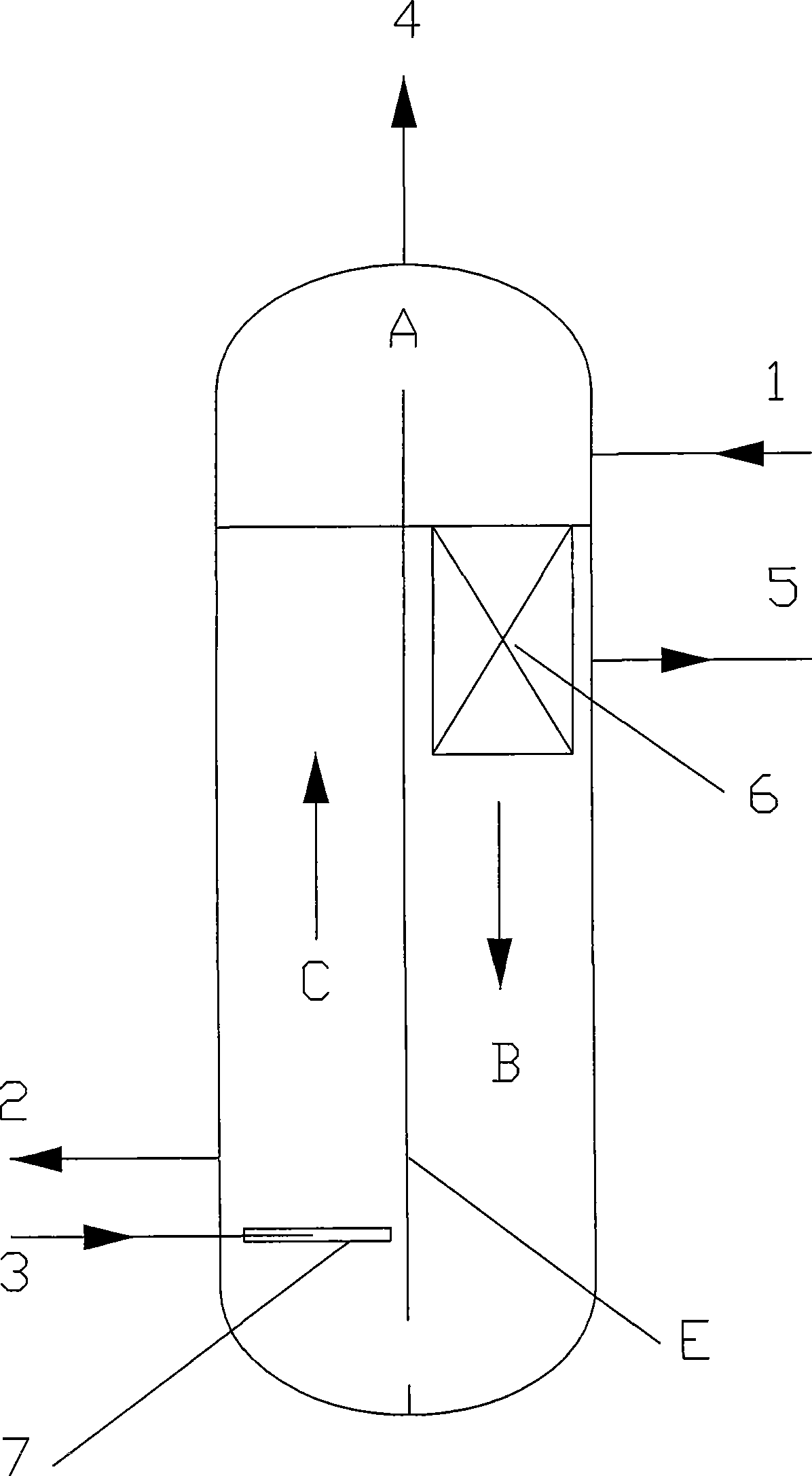
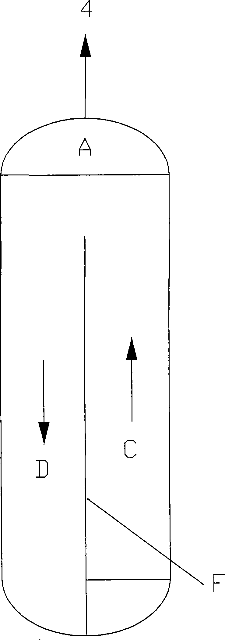
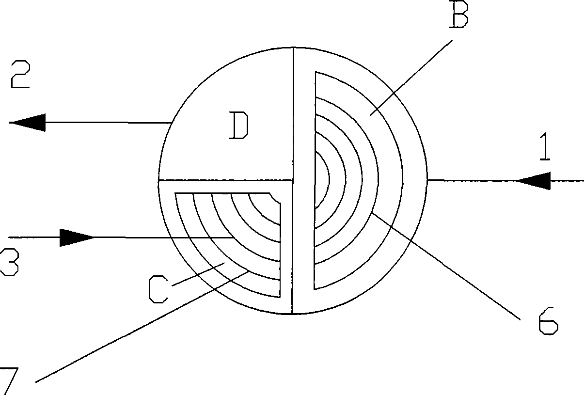
[0054] The area volume ratio of the separation device is tail gas separation zone: oil-alkali separation zone: gas lift separation zone: lye stabilization zone = 15:40:25:20. The lye entering the device is the lye after traditional air oxidation, the effective alkali concentration is 11.7%wt, the disulfide content is 9744ppm, the lye flow rate is 100L / h, and the air stripping gas flow rate is 35L / h. The disulfide content of the lye from the device is 1926ppm.

example 2

[0056] The area volume ratio of the separation device is tail gas separation zone: oil-alkali separation zone: gas lift separation zone: lye stabilization zone = 15:40:25:20. The lye fed into the device is the lye after traditional air oxidation, the effective alkali concentration is 11.7%wt, the disulfide content is 9744ppm, the lye flow rate is 100L / h, and the air stripping gas flow rate is 60L / h. The disulfide content of the lye from the device is 1542ppm.

example 3

[0058] The area volume ratio of the separation device is tail gas separation zone: oil-alkali separation zone: gas lift separation zone: lye stabilization zone = 15:40:25:20. The lye into the device is lye after oxygen-enriched room temperature oxidation, the effective alkali concentration is 23.9%wt, the disulfide content is 18978ppm, the lye flow rate is 100L / h, and the gas stripping gas flow rate is 35L / h. The disulfide content of the lye from the device is 1594ppm.


PUM


Abstract

The invention relates to an oil-contained lye separating device, which at least comprises a device shell and is characterized in that the upper space of the device shell is a tail gas separation zone provided with a tail gas outlet, and the circumferential surface of the middle-lower space of the device shell is at least distributed with an oil-alkali separation zone provided with an oxidized lyeinlet and a gas stripping separation zone, wherein an oil phase aggregation separating device and an oil phase outlet are arranged in the oil-alkali separation zone which is communicated with the bottom of the gas stripping separation zone; a gas distributor and a gas stripping gas inlet connected therewith are arranged in the gas stripping separation zone; and the device shell is provided with aregenerated lye outlet. A method comprises the following steps: adopting the oil phase aggregation separating device to perform oil-alkali separation on the oxidized lye in the oil-alkali separation zone, and then using the gas distributor to perform gas stripping in the gas stripping zone so as to obtain the regenerated lye through a lye stabilization zone, wherein the tail gas zone is communicated with other zones so as to exhaust the tail gas after the treatment. The oil-contained lye separating device integrates the separation processes of the three phases including the tail gas generatedin the lye regeneration process, the lye and disulphide into a whole; the cleanliness of the lye obtained through separation is improved, the content of the disulphide is low, and the separation effect is good; besides, the oil-contained lye separating device has the advantages of more compact structure, small volume, and reasonable and practical process.

Description

Technical field [0001] The invention relates to an oil-containing lye separation device and method. The method and the device belong to the technical field of product refining technology and device separation in the field of petroleum and natural gas processing. Background technique [0002] In the refining process of liquefied gas, the mercaptans are removed through the alkaline washing process to achieve the total sulfur content of the liquefied gas to meet the requirements of national standards or enterprise internal control standards. The mercaptan in the liquefied gas reacts with sodium hydroxide to form sodium mercaptide, and the concentration of sodium hydroxide in the lye decreases. The lye rich in sodium mercaptide can be regenerated through oxidation process. Under the action of the catalyst sulfonated cobalt phthalocyanide, the sodium mercaptide reacts with oxygen to produce sodium hydroxide and disulfide. The disulfide is separated from the lye, and the regenerated ly...

Claims


Application Information

Patent Timeline
IPC IPC(8): C10G19/02C10G19/08B01D17/025
Inventor 聂通元王铭
Owner NINGBO ZHONGYI PETROCHEM TECH
Why Eureka
Try Eureka