Control method resonant cavity enhancement detector cavity film

A control method and detector technology, applied in the field of optical detectors and infrared detection, to achieve the effects of improving utilization, improving quantum efficiency, and saving costs

Inactive Publication Date: 2009-07-01
INST OF SEMICONDUCTORS - CHINESE ACAD OF SCI
View PDF0 Cites 3 Cited by
  • Summary
  • Abstract
  • Description
  • Claims
  • Application Information

AI Technical Summary

Problems solved by technology

[0006] The purpose of the present invention is to provide a method for controlling the cavity mode of a resonance-enhanced detector. By using this method, the matching problem between the wavelength corresponding to the high

Method used


Image

  • Control method resonant cavity enhancement detector cavity film
  • Control method resonant cavity enhancement detector cavity film
  • Control method resonant cavity enhancement detector cavity film

Examples


Embodiment Construction

[0023] In order to make the object, technical solution and advantages of the present invention clearer, the present invention will be described in further detail below in conjunction with specific embodiments and with reference to the accompanying drawings.

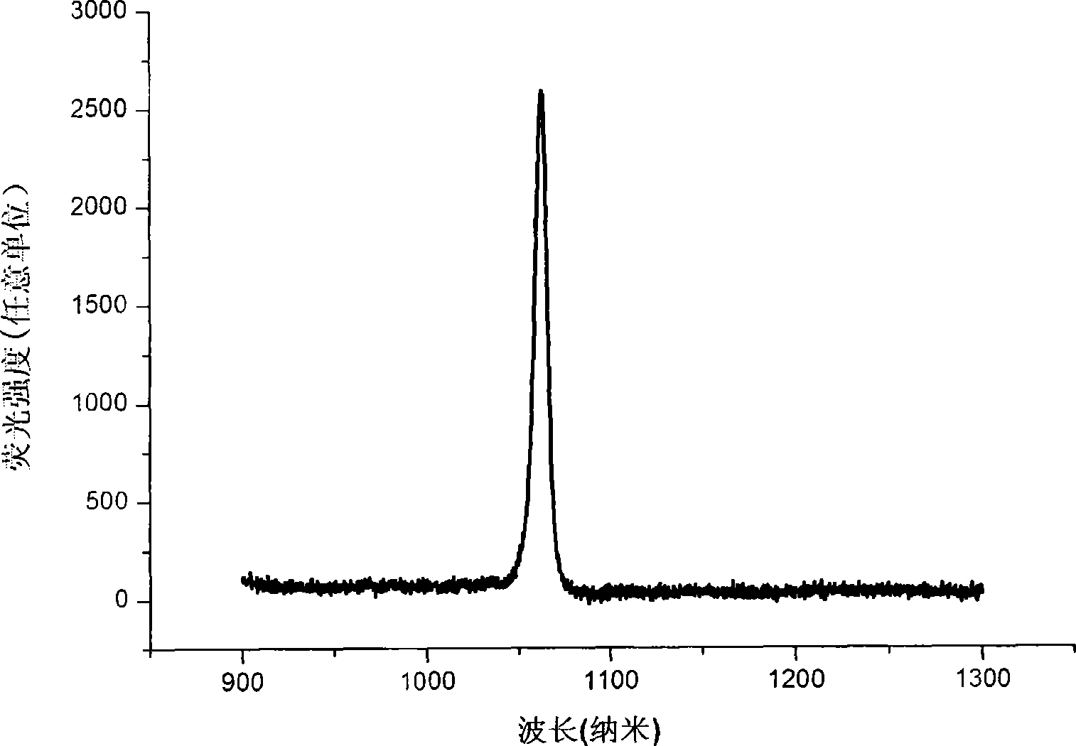
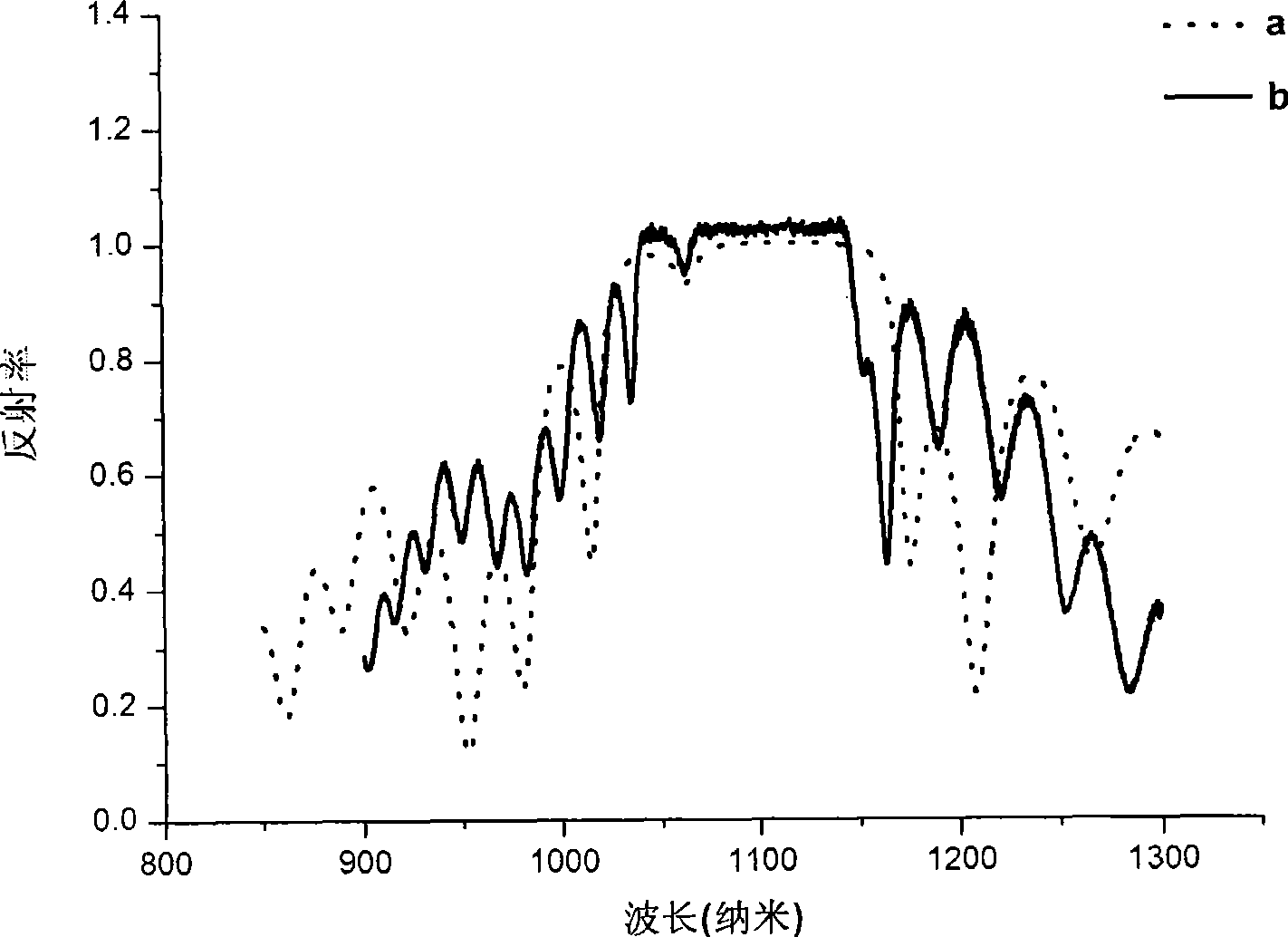
[0024] The cavity mode position of the resonance enhanced detector designed in the present invention is at 1064nm, and quantum dots are designed to grow at the antinode position of the cavity. The object of the present invention is to make the position of the cavity mode of the resonance enhanced detector be at 1064nm, and the center wavelength corresponding to the high antiband of the cavity mode matches the wavelength corresponding to the length of the cavity.

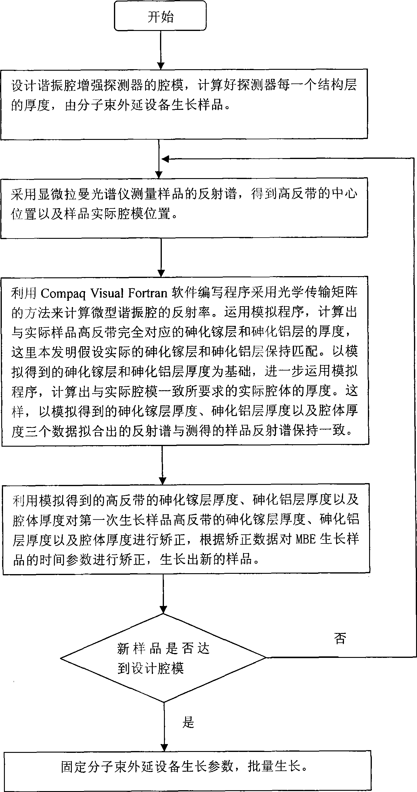
[0025] see figure 1 , figure 1 It is a flow chart of the present invention, and a control method of a resonant cavity-enhanced detector cavity mode of the present invention comprises the following steps:

[0026] Step 1: Design the cavity mode of the resonant ...


PUM


Abstract

The invention relates to a method for controlling a cavity module of a resonant cavity reinforcing detector, which comprises: firstly, designing a cavity module of the resonant cavity reinforcing detector, initially setting the thickness of each structure layer of the detector, and leading samples to grow on a molecular beam epitaxy device, secondly, adopting a confocal laser Raman microscopy to measure reflectance spectrums of samples, and getting central positions of a high reflectivity belt and an actual cavity module position of a sample, thirdly, adopting an analog procedure, calculating out the thickness of a gallium arsenide layer which is totally corresponding to the high reflectivity belt of an actual sample, the thickness of an aluminium arsenide layer and the thickness of an actual cavity body, required by totally corresponding to the actual cavity module, fourthly, correcting the thickness of the gallium arsenide layer of the high reflectivity belt where samples firstly grow, the thickness of the aluminium arsenide layer and the thickness of the cavity body according to the data got through the step three, and correcting time parameters for growing samples on the molecular beam epitaxy, and leading new samples to grow, fifthly, adopting the confocal laser Raman microscopy to measure reflectance spectrums of new samples.

Description

technical field [0001] The invention relates to the field of optical detectors, in particular to the technical field of infrared detection, and provides a method for controlling cavity modes of resonant cavity enhanced detectors. The invention can be applied in the growth control technology of the resonant cavity enhanced type detector. Background technique [0002] All objects emit thermal radiation related to their temperature and properties, with most of the thermal radiation from objects near ambient temperature in the infrared band. Infrared radiation occupies a fairly wide electromagnetic wave band (0.8 μm ~ 1000 μm). It can be seen that infrared radiation provides rich information of the objective world, and making full use of this information is the goal pursued by people. Devices that convert invisible infrared radiation into a measurable signal are infrared detectors. As the core key component of the infrared complete system, the detector detects, identifies and...

Claims


Application Information

Patent Timeline
IPC IPC(8): H01L31/18G05D5/02G01J3/44
CPCH01J23/20G01N21/65
Inventor 孙晓明郑厚植章昊甘华东朱汇谈笑天肖文波李韫慧
Owner INST OF SEMICONDUCTORS - CHINESE ACAD OF SCI
Why Eureka
Try Eureka