

Testing method of wavelength-tunable laser, controlling method of wavelength-tunable laser and laser device
A control method and laser technology, applied in the direction of lasers, laser components, semiconductor lasers, etc., can solve problems such as prolonged assembly time, difficulty in reducing size, and influence of adjustable laser parameter changes
- Summary
- Abstract
- Description
- Claims
- Application Information
AI Technical Summary
Problems solved by technology
Method used
Image

Examples
no. 1 approach
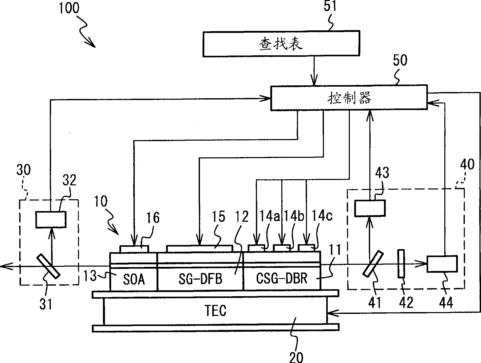
[0045] figure 2 A schematic diagram illustrating the wavelength tunable laser 10 and the laser device 100 having the wavelength tunable laser 10 according to the first embodiment is illustrated. Such as figure 2 As shown, the laser device 100 has a wavelength tunable laser 10 , a temperature control device 20 , an output detector 30 , a wavelength detector 40 and a controller 50 . The wavelength tunable laser 10 is located on the temperature control device 20 . Each component will be described in detail below.
[0046] The wavelength tunable laser 10 has the following structure, in which a chirped sampled grating distributed reflector (CSG-DBR) region 11, a sampled grating distributed feedback laser (SG-DFB) region 12 and a semiconductor optical amplifier (SOA) area 13.
[0047] The CSG-DBR region 11 has an optical waveguide having a plurality of segments in which a first region having a diffraction grating and a second region connected to the first region and serving as...
no. 2 approach
[0142] Figure 16 A schematic diagram of a laser device 100a according to the second embodiment is illustrated. The laser device 100 a differs from the laser device 100 in that a wavelength tunable laser 10 a is provided instead of the wavelength tunable laser 10 .
[0143] Such as Figure 16 As shown, the wavelength tunable laser 10a has the following structure, in which the SG-DBR (sampling grating distributed Bragg reflector) region 21, PS (phase shift) region 22, gain region 23, SG- DBR zone 24 and SOA zone 13.
[0144] The SG-DBR regions 21 and 24 have an optical waveguide having a plurality of segments in which a first region having a diffraction grating and a second region connected to the first region and serving as a spacer are provided. The optical waveguide is made of a semiconductor crystal having an absorption edge wavelength on the shorter wavelength side than the laser oscillation wavelength. Within the SG-DBR regions 21 and 24, each second region has the sa...
no. 3 approach
[0149] Figure 17 A schematic diagram of a laser device 100b according to the third embodiment is illustrated. Such as Figure 17 As shown, the laser device 100 b has a gain element 10 b consisting of a gain region 61 and a PS region 62 . A fixed etalon 67 and a liquid crystal mirror 66 are sequentially provided on the side of the PS region 62 of the gain element 10b. The fixed etalon 67 is an optical etalon with periodic transparent wavelength peaks. The liquid crystal mirror 66 has a structure in which a liquid crystal etalon is integrated with a mirror to form a resonator between the mirror and the end face of the gain region 61 . Here, the liquid crystal etalon has an optical etalon structure in which a liquid crystal region is sealed, and the refractive index of the liquid crystal can be controlled using a voltage. The liquid crystal mirror 66 according to this embodiment has a liquid crystal etalon whose wavelength peak is not used to fix the wavelength peak of the e...
PUM
 Abstract
Description
Claims
Application Information