
Automatic feeding apparatus preparing pool for powdered activated charcoal

A technology of powder activated carbon and blending pool, which is applied in the direction of adsorption water/sewage treatment, etc. It can solve the problems of simple equipment, uneven pulping, and low dosing efficiency, so as to avoid deposition, improve the working environment, and increase the utilization rate.

Inactive Publication Date: 2009-07-08
上海环境保护有限公司
View PDF0 Cites 26 Cited by
  • Summary
  • Abstract
  • Description
  • Claims
  • Application Information

AI Technical Summary

Problems solved by technology

[0005] However, at present, the technology of domestic waterworks is relatively old and the equipment is simple. The traditional dosing methods of powdered activated carbon are mostly manual dosing (manual weighing of chemicals) or simple mechanical dosing. Since powdered activated carbon is put into water after simple stirring and pulping, this There are great defects in the application of this process:
[0006] 1. It is difficult to control the dosage, the dosage operation is not accurate, and the dosage efficiency is low
[0007] 2. Simple stirring, uneven pulping, and will cause carbon powder to deposit in dead corners, resulting in serious waste
[0008] 3. Insufficient stirring, poor dispersibility of the agent, easy agglomeration, and poor dosing effect
[0009] 4. Simple equipment for metering, dosing and pulping, poor sealing performance, flying dust, and harsh working environment

Method used


Image

  • Automatic feeding apparatus preparing pool for powdered activated charcoal
  • Automatic feeding apparatus preparing pool for powdered activated charcoal
  • Automatic feeding apparatus preparing pool for powdered activated charcoal

Examples


Embodiment Construction

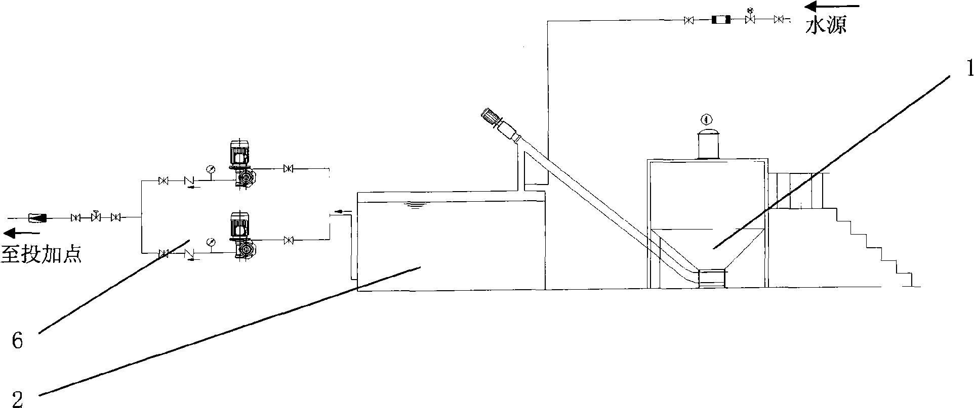
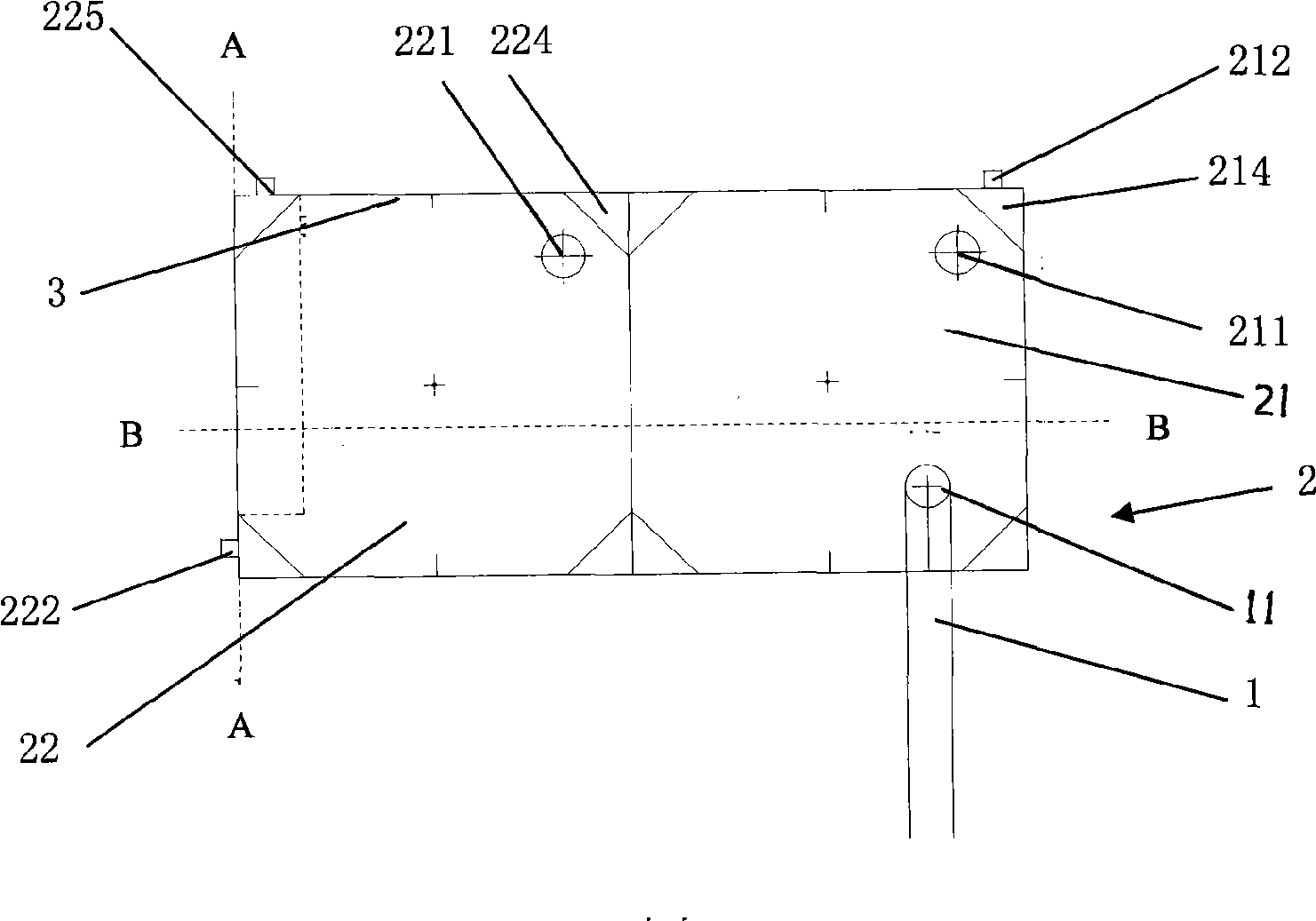
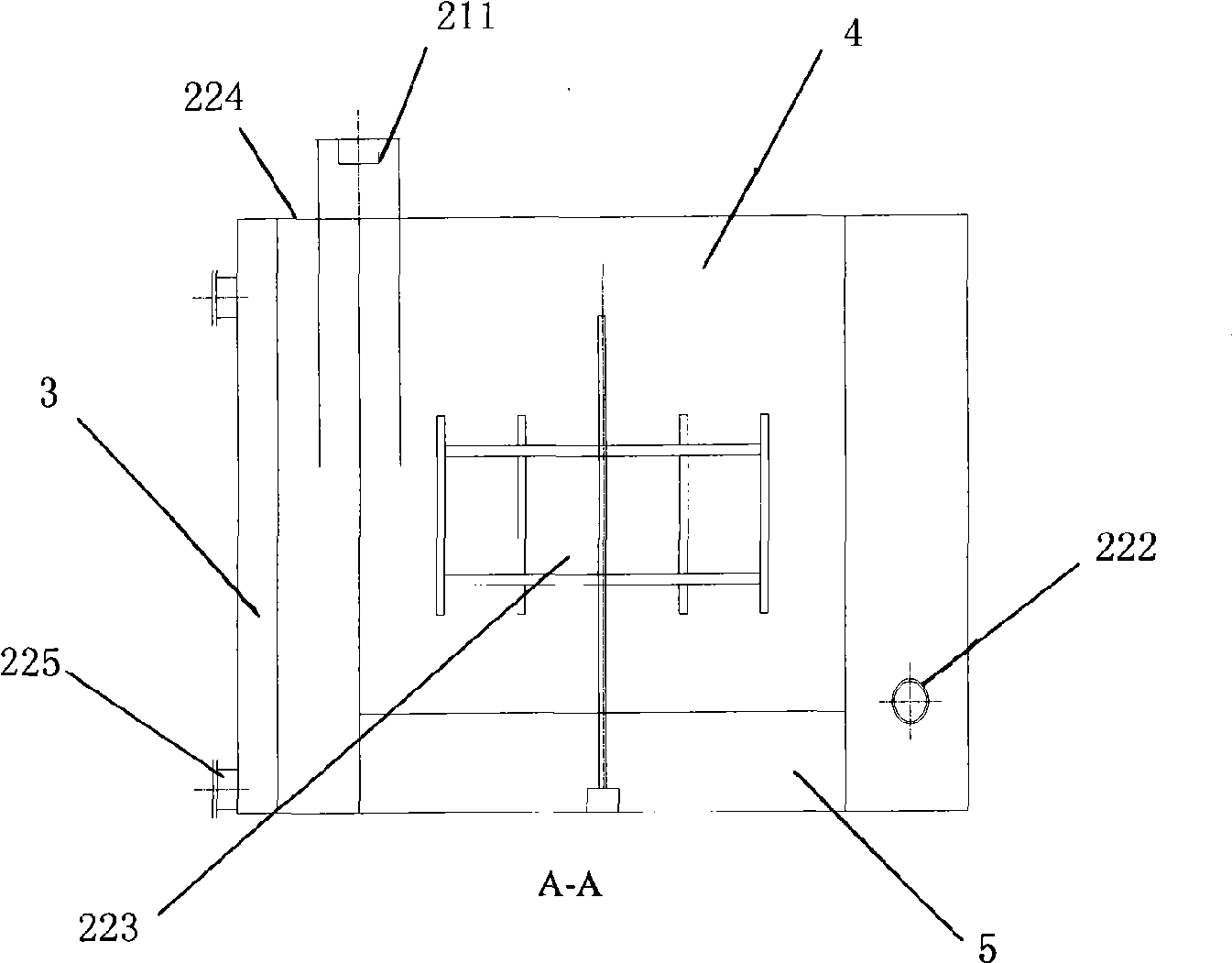
[0036] see figure 1 It is the structural representation of powder activated carbon automatic dosing equipment of the present invention, figure 2 It is a schematic diagram of the top view structure of the two-stage blending pool of the present invention, image 3 for figure 2 The A-A cross-sectional structure schematic diagram and Figure 4 for figure 2 As shown in the B-B cross-sectional structural schematic diagram of , a blending pool for automatic powdered activated carbon dosing equipment is a two-stage blending pool 2, including a first blending pool 21 and a second blending pool 22, and the ratio of its length, width, and height is 3. : 3: 2, the two-stage blending pool 2 is located at the front end of the dosing device 6, the first blending pool 21 and the second blending pool 22 are equipped with stirring devices, the feeding port 11 of the feeding device 1 is connected to the first blending The tanks 21 are sealed and connected, the first mixing tank 21 is prov...


PUM


Abstract

The invention provides a blending tank of automatic adding equipment for powdered activated carbon. The blending tank is arranged at the front end of the adding equipment; a stirring device is arranged in the blending tank; powdered activated carbon is fed into the blending tank through a feeding device, stirred and made into carbon-in-pulp; and the carbon-in-pulp is conveyed to a coagulation tank and added through the adding equipment, wherein the blending tank is a two-segment type blending tank; a feeding port of the feeding device is connected with a first blending tank; a flow-reducing type impeller stirring device is arranged in the first blending tank; a baffle is arranged between the first blending tank and a second blending tank; the first blending tank and the second blending tank are communicated through the water-passing end face of the bottom of the baffle; a paddle-board type stirring device is arranged in the second blending tank; and a material outlet of the second blending tank is connected with the adding equipment. The blending tank has the advantages that the blending tank adopts the two-segment type blending tank is adopted, improves the mixture uniformity of the powdered activated carbon and water through primary stir and then intensive stir so as to achieve deep blending, is provided with a flow disturbing baffle to ensure the intensive mixing of the activated carbon and water in a turbulence state, produces no dust in the process of adding dust, and improves working environment.

Description

technical field [0001] The invention belongs to the fields of environmental protection science and engineering, mechanical engineering and construction engineering, and relates to water treatment equipment, in particular to a mixing tank for automatic powder activated carbon dosing equipment. Background technique [0002] With the development of modern industry, agriculture and other industries, the pollution of drinking water sources that human beings depend on is becoming more and more serious. The types and quantities of pollutants in the water are increasing, and the pollution components are becoming more and more complex. It can no longer meet the requirements and must be processed in depth. [0003] At present, in the United States, Europe, Japan and other developed countries and regions, the advanced treatment process in the water supply system is relatively mature. Among them, activated carbon is used as a high-efficiency adsorbent, which not only has strong adsorpt...

Claims


Application Information

Patent Timeline
Patent Type & Authority Applications(China)
IPC IPC(8): C02F1/28
Inventor 邢绍文曹卫承刘利何校初黄智伟
Owner 上海环境保护有限公司
Learn More