Magneto-optic rotation reinforced device

A magneto-optical rotation and optical intensifier technology, applied in optics, instruments, nonlinear optics, etc., can solve the problems of increasing the complexity of measuring devices, unfavorable instrument miniaturization, small sample volume, etc., and achieves simple structure, easy production, Effects suitable for integration

Active Publication Date: 2009-07-22
SHANGHAI MUNICIPAL ELECTRIC POWER CO +1
View PDF0 Cites 8 Cited by
  • Summary
  • Abstract
  • Description
  • Claims
  • Application Information

AI Technical Summary

Problems solved by technology

The problem with the microfluidic system is that the sample volume is small and the optical path is severely limited. In order to measure the small optical rotation angle, the method of polarization modulation can be used [3], but this...

Method used


Image

  • Magneto-optic rotation reinforced device
  • Magneto-optic rotation reinforced device

Examples


specific Embodiment 1

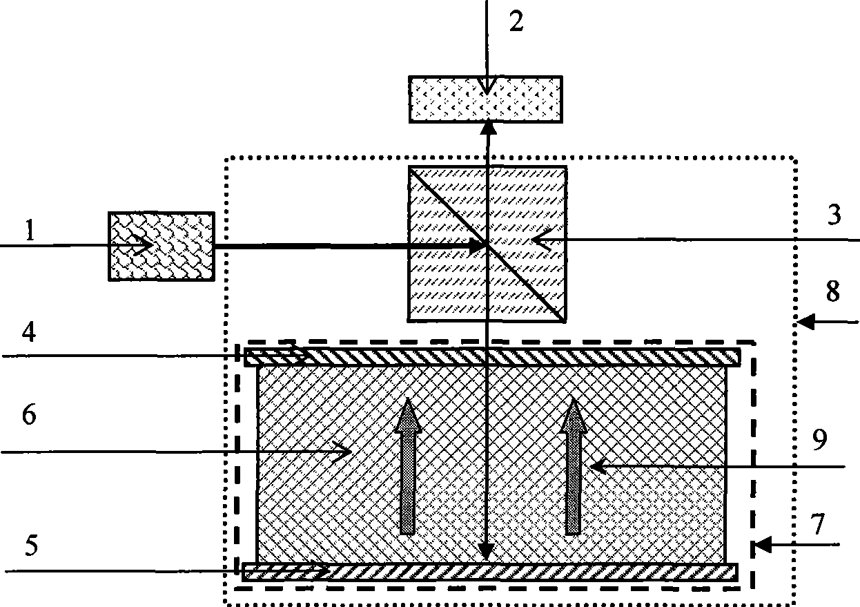
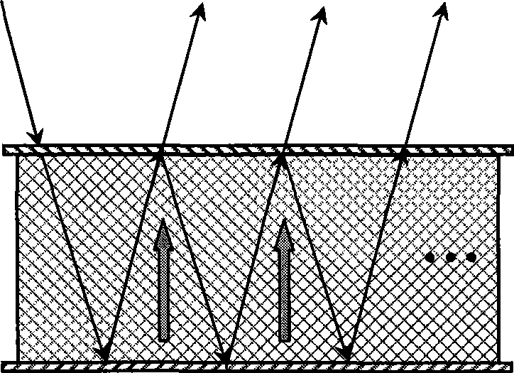
[0024] Specific embodiment 1: The present invention proposes a microfluidic magneto-induced optical rotation enhancement device, the optical rotation enhancer 8 is composed of an optical rotation reflection cavity 7 and a polarization beam splitting prism 3 located outside the optical rotation reflection cavity 7; the optical rotation reflection cavity 7 is composed of The partial reflection mirror 4 and the total reflection mirror 5 placed in parallel and the magneto-optical medium 6 between them are composed. When the optical path through the sample is fixed, a magnetic field 9 is added along the direction of light propagation. According to the non-reciprocity of the magneto-optic effect The sensitivity of measuring the small rotation angle is improved through the optical rotation intensifier 8; the light source 1 is located next to the polarizing beam splitter prism 3.


PUM


Abstract

A micro-fluidic faraday rotation reinforcer relates to a novel micro-fluidic faraday rotation reinforcer structure. The rotation reinforcer (8) consists of a rotation reflection cavity (7) and a polarized beam splitter prism (3) outside the rotation reflection cavity (7); wherein the rotation reflection cavity (7) consists of a partially reflecting mirror (4) and a total reflecting mirror (5) which are parallelly arranged and a magneto-optic medium (6) between the partially reflecting mirror (4) and the total reflector (5); when the light path passing through a sample is constant, a magnetic field (9) is added along the light propagation direction; according to the nonreciprocity of magnetooptical effect, the rotation reinforcer (8) is used for improving measuring sensitivity to micro rotation angle; and a light source (1) is arranged beside the polarized beam splitter prism (3). According to the nonreciprocity of Faraday magnetooptical effect, when the beam passes through the sample medium back and forth for a plurality of times, the rotation angle can be multiplied. The micro-fluidic reinforcer designed by the invention has the advantages of simple structure, easy manufacture and convenient integration.

Description

technical field [0001] The patent of the invention relates to a novel microfluidic magneto-optical rotation enhancement device structure and its working principle, which belongs to the technical field of optical detection and optical information processing devices. Background technique [0002] Microfluidic optics is a new technology of great significance. It combines modern microfluidic technology and micro-optoelectronics technology to develop a class of optical integrated devices and The system will have important application prospects in the fields of sensing, communication, and information processing [1]. [0003] The miniaturization and integration of microfluidic optical detection system is the development trend of microfluidic technology [1], and the optical detection of microfluidic substances is also one of the important research topics of microfluidic optical technology [2]. For fluid media containing paramagnetic and diamagnetic substances, the concentration of ...

Claims


Application Information

Patent Timeline
IPC IPC(8): G02F1/09G01N21/21
Inventor 赵瑞梁忠诚
Owner SHANGHAI MUNICIPAL ELECTRIC POWER CO
Why Eureka
Try Eureka