Anaerobic reactor

An anaerobic reactor and cylinder technology, which is applied in the field of anaerobic reactors, can solve the problems of reducing the rising flow rate of sewage surface, easy blockage and agglomeration of fillers, and large volume of the reactor, so as to improve the utilization rate of equipment volume, strengthen the The effect of mixing and contact, simplifying the water distribution structure

Active Publication Date: 2010-12-29
WELLE ENVIRONMENTAL GRP CO LTD
View PDF1 Cites 2 Cited by
  • Summary
  • Abstract
  • Description
  • Claims
  • Application Information

AI Technical Summary

Problems solved by technology

(3) High content of ammonia nitrogen
(4), high metal content
There are mainly the following problems: 1. The water distribution effect is not good
However, on the one hand, this structure is complex and takes up a lot of space; on the other hand, since the water distribution is realized through the distribution head of the distribution tank, the water pressure decreases, which reduces the rising velocity of the sewage surface and affects the mixing of sludge and leachate.
2. The structure of the whole system is complex
In order to reduce the pollutant load of the influent water, the anaerobic treated water is mixed and diluted with the landfill leachate through the return pump and then enters the cylinder. Therefore, the water inlet pipe and the return pipe are operated independently by their own pumps, while the dosing pipe is directly connected to the cylinder. Body connection, there is a problem of inconvenient adjustment
In addition, it needs to pass through a three-phase separator, resulting in a bulky reactor
3. Uneven mud discharge
Due to the single-point sludge discharge, the uneven sludge discharge will interfere with the flow state in the reactor, affect the mud-water separation effect in the clarification zone, and affect the stability of the treatment
4. The filler is easy to block and agglomerate
When the leachate is distributed on the bottom of the whole cylinder through the distribution device and flows from bottom to top, the soft packing will be displaced by the hydraulic impact, causing blockage and agglomeration, which will affect the treatment effect

Method used


Image

  • Anaerobic reactor
  • Anaerobic reactor
  • Anaerobic reactor

Examples


Embodiment Construction

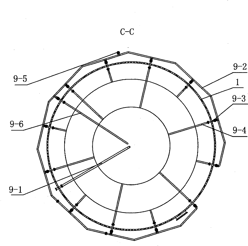
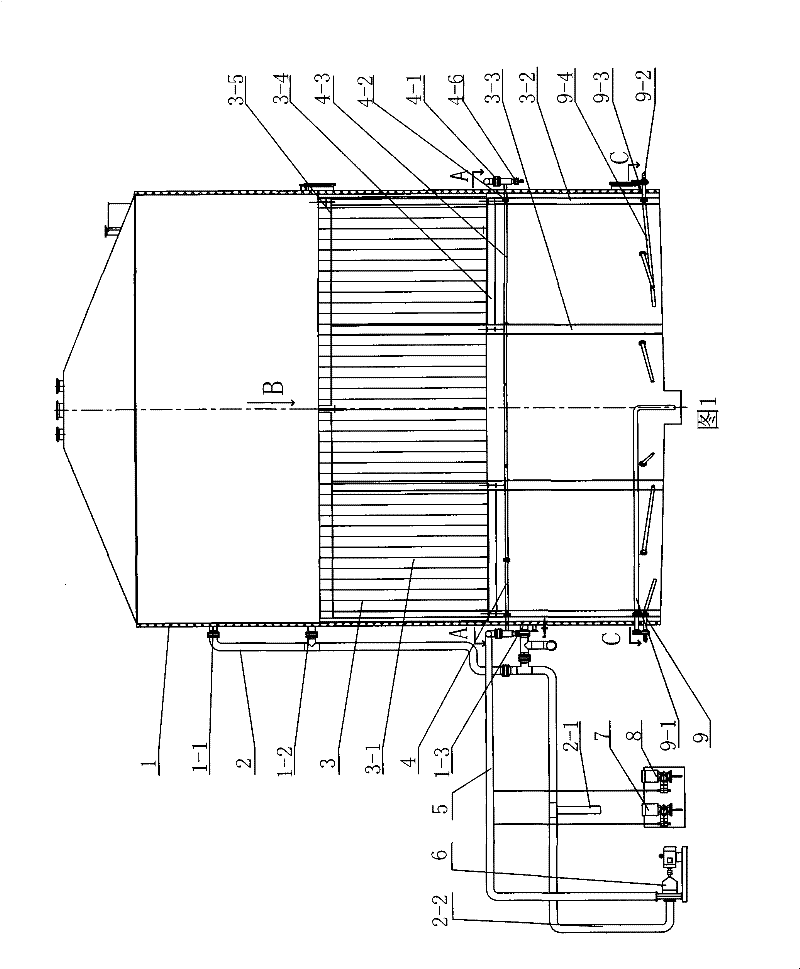
[0023] As shown in FIG. 1 , the anaerobic reactor of the present invention includes a cylinder body 1 , a water inlet pipe 5 , a water outlet pipe 2 , a water distribution device 4 , a packing device 3 and a sludge discharge device 9 .

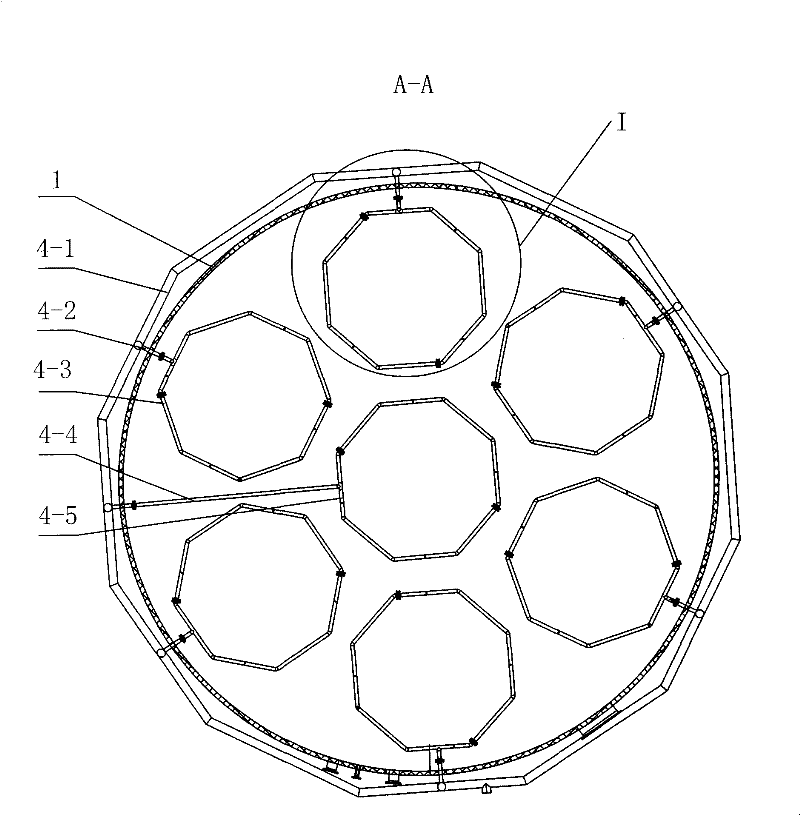
[0024] As shown in Figures 1-3, the water distribution device 4 of the present invention is located at the bottom of the packing device 3, above the sludge suspension layer. The water distribution device 4 includes a water distribution main pipe 4-1 and a water distribution branch pipe 4-3. The water distribution main pipe 4-1 is connected to the water inlet pipe 5 through the water inlet. The water distribution main pipe 4-1 is provided with a flushing joint 4-6, which can The water distribution branch pipe 4-3 is flushed with medicine, which solves the problem of easy blockage of the water distribution device. In the present invention, the water distribution main pipe 4-1 is arranged on the outer periphery of the cylinder body 1, the water d...


PUM


Abstract

The invention relates to an anaerobic reactor. The anaerobic reactor comprises a cylinder body, a water inlet pipe, a water outlet pipe, a filling device on the middle part of the water outlet pipe, a water distribution device at the bottom of the filling device and a sludge discharge device at the bottom of the water distribution device; the water distribution device comprises a water distribution main pipe and more than four closed annular water distribution branch pipes; water outlet holes of the water distribution branch pipes are alternately arranged along more than three concentric circumferences; the cylinder body is positioned on the upper part of the filling device; the lower part of each water distribution branch pipe is provided with more than two water outlets; the water outlets are connected with the water outlet pipe; a reflowing pipe of the water outlet pipe is mixed with the water inlet pipe by a circulating pump and is communicated with the water distribution main pipe; a first medicating device and a second medicating device are communicated with the water inlet pipe respectively through connecting pipes; the filling device comprises a filling rack, a membrane hanging rack and a zonal biomembrane strip; the biomembrane strip is hung on the membrane hanging rack; and the sludge discharge device comprises a sludge discharge main pipe and six sludge discharge branch pipes arranged in length alternation along radial direction. The anaerobic reactor has the characteristics of reasonable water distribution, compact structure and stable operation of the reactor.

Description

technical field [0001] The invention relates to an anaerobic reactor, which belongs to the technical field of landfill leachate treatment. Background technique [0002] When the garbage is treated by incineration, it usually goes through a one-week aging process to reduce the moisture content of the garbage, and a certain amount of leachate will be generated during the aging process. The landfill leachate of the incineration plant mainly has the following characteristics: (1) There are many types of organic matter and high concentration, and the concentration changes greatly. The landfill leachate of the incineration plant is mostly the landfill leachate of the day without obvious biochemical action, so it contains a large amount of organic compounds such as heterocyclic aromatic hydrocarbon compounds, alcohol compounds and aniline compounds. The COD value is usually 40000mg / L-80000mg / between L. (2), good biochemical properties. The landfill leachate of the incinerator i...

Claims


Application Information

Patent Timeline
Patent Type & Authority Patents(China)
IPC IPC(8): C02F3/28
Inventor 李月中浦燕新周丽烨朱卫兵
Owner WELLE ENVIRONMENTAL GRP CO LTD
Why Eureka
Try Eureka