
Wideband substrate integrated ridge waveguide and analyzing method thereof

A substrate-integrated waveguide and substrate-integrated technology, applied in waveguides, waveguide-type devices, circuits, etc., can solve the problems of substrate-integrated waveguide bandwidth widening technology research, use restrictions, narrow bandwidth, etc., to achieve light weight, reduce Effect of circuit size and high Q factor

Inactive Publication Date: 2009-08-05
NANJING UNIV OF SCI & TECH
View PDF0 Cites 9 Cited by
  • Summary
  • Abstract
  • Description
  • Claims
  • Application Information

AI Technical Summary

Problems solved by technology

[0004] However, the current substrate-integrated waveguide has a narrow bandwidth in practical applications, especially in broadband microwave and millimeter-wave systems, and cannot meet the requirements of engineering applications, so its use is limited to a certain extent.
So far, no one has studied the bandwidth extension technology of substrate-integrated waveguides

Method used


Image

  • Wideband substrate integrated ridge waveguide and analyzing method thereof
  • Wideband substrate integrated ridge waveguide and analyzing method thereof
  • Wideband substrate integrated ridge waveguide and analyzing method thereof

Examples


Embodiment Construction

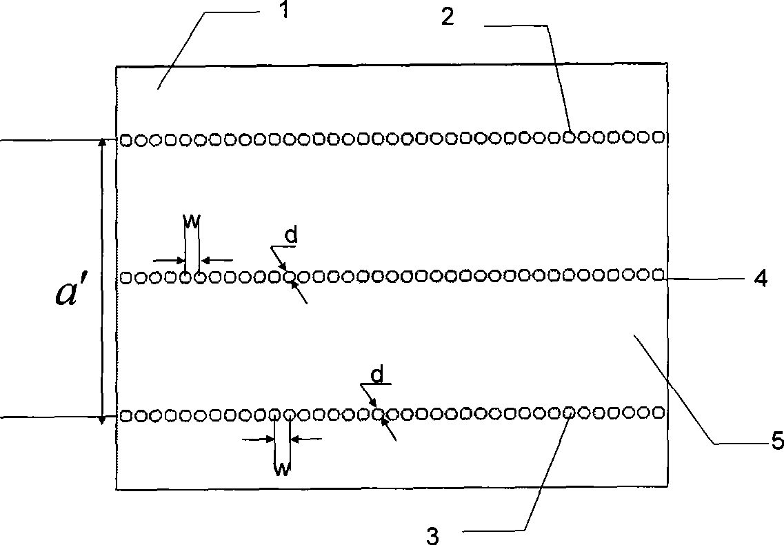
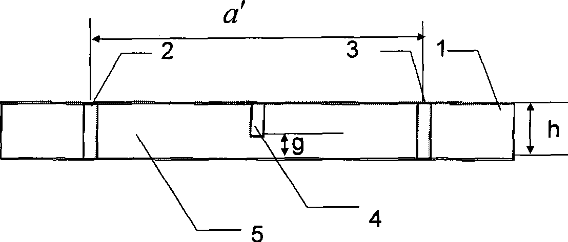
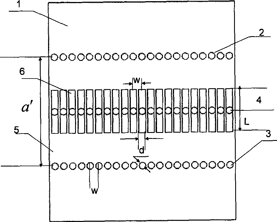
[0024] combine figure 1 , the broadband substrate integrated ridge waveguide of the present invention includes a dielectric substrate 1, and two rows of metal pillars 2 and 3 are arranged on the dielectric substrate 1 to form a substrate integrated waveguide 5. The middle position of the two rows of metal pillars 2 and 3 is A row of intermediate ridge metal pillars 4 is provided, and the intermediate ridge metal pillars 4 are vertically embedded in the dielectric substrate 1. The upper surface of the intermediate ridge metal pillars coincides with the upper surface of the dielectric substrate 1, and the lower bottom surface of the intermediate ridge metal pillars 4 is located in the dielectric substrate 1. There is a gap g between the inside of the substrate 1 and the lower bottom surface of the dielectric substrate 1 .

[0025] In the broadband substrate integrated ridge waveguide of the present invention, the dielectric substrate 1 is composed of ten layers of media with a t...


PUM


Abstract

The invention discloses a broadband substrate integrated ridge waveguide and an analysis method thereof. The broadband substrate integrated ridge waveguide comprises a medium substrate; two rows of metal columns are arranged on the medium substrate to form a substrate integrated waveguide; a row of middle ridge metal columns are arranged between the two rows of metal columns and vertically embedded into the medium substrate; the upper surfaces of the middle ridge metal columns are superimposed with the upper surface of the medium substrate; and the lower surfaces of the middle ridge metal columns are arranged in the medium substrate and form a gap g with the lower bottom surface of the medium substrate. The invention reduces the cut-off frequency of a principal mode and improves the bandwidth of the waveguide. The simple theoretical analysis method realizes higher accuracy. A row of metal strips with the identical spacing are added into the lower ends of the suspended metal columns soas to introduce novel capacitance, thereby improving the bandwidth. The invention has the significant advantages of small volume, light weight, low loss and easy integration with other planar microwave millimeter-wave circuits. The working bandwidth of the principal mode is greatly improved, thereby greatly broadening the scope of application.

Description

technical field [0001] The invention belongs to a novel transmission line in a microwave and millimeter wave hybrid integrated circuit and a millimeter wave integrated circuit, in particular to a broadband substrate integrated ridge waveguide and an analysis method thereof. Background technique [0002] The traditional rectangular waveguide is a waveguide device for transmitting electromagnetic energy, which can reduce transmission loss and prevent electromagnetic waves from radiating outward, so that the guided electromagnetic wave is completely confined to the metal conduit, with large power capacity, high Q value, and easy processing. However, the rectangular waveguide is bulky, and its three-dimensional structure is difficult to integrate with planar circuits. The development of modern technology has very high requirements for miniaturization and integration. As the most widely used planar transmission line, the microstrip line is small in size and light in weight, and ...

Claims


Application Information

Patent Timeline
Patent Type & Authority Applications(China)
IPC IPC(8): H01P3/123
Inventor 车文荃李翠霞周雍王超汪磊李超
Owner NANJING UNIV OF SCI & TECH
Learn More