Cylinder tube-type sound wave comprehensive function coprocessor
A co-processor and cylinder technology, applied in the field of ultrasonic applications, can solve problems such as unguaranteed product quality, uneven ultrasonic cavitation, and unstable quality, and achieve quality assurance, stable processing, and obvious effects
- Summary
- Abstract
- Description
- Claims
- Application Information
AI Technical Summary
Problems solved by technology
Method used
Image
Examples
Embodiment 1
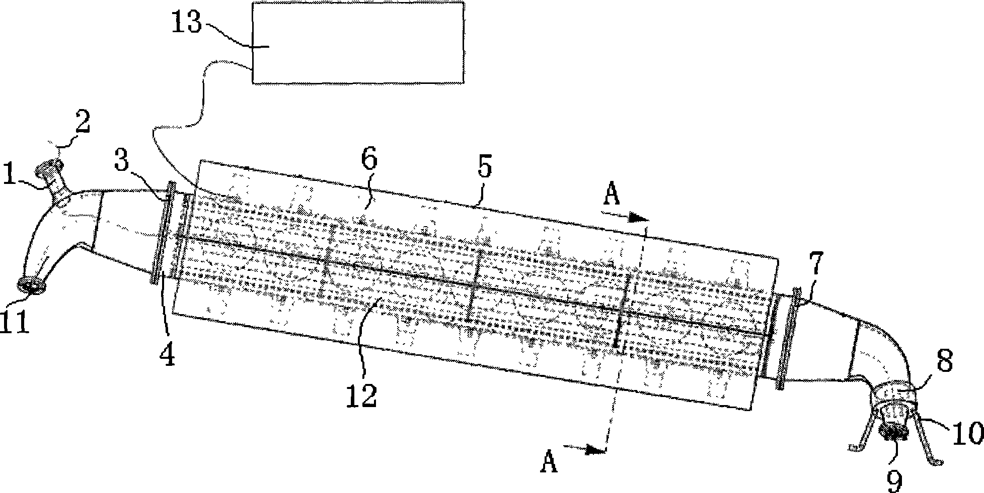
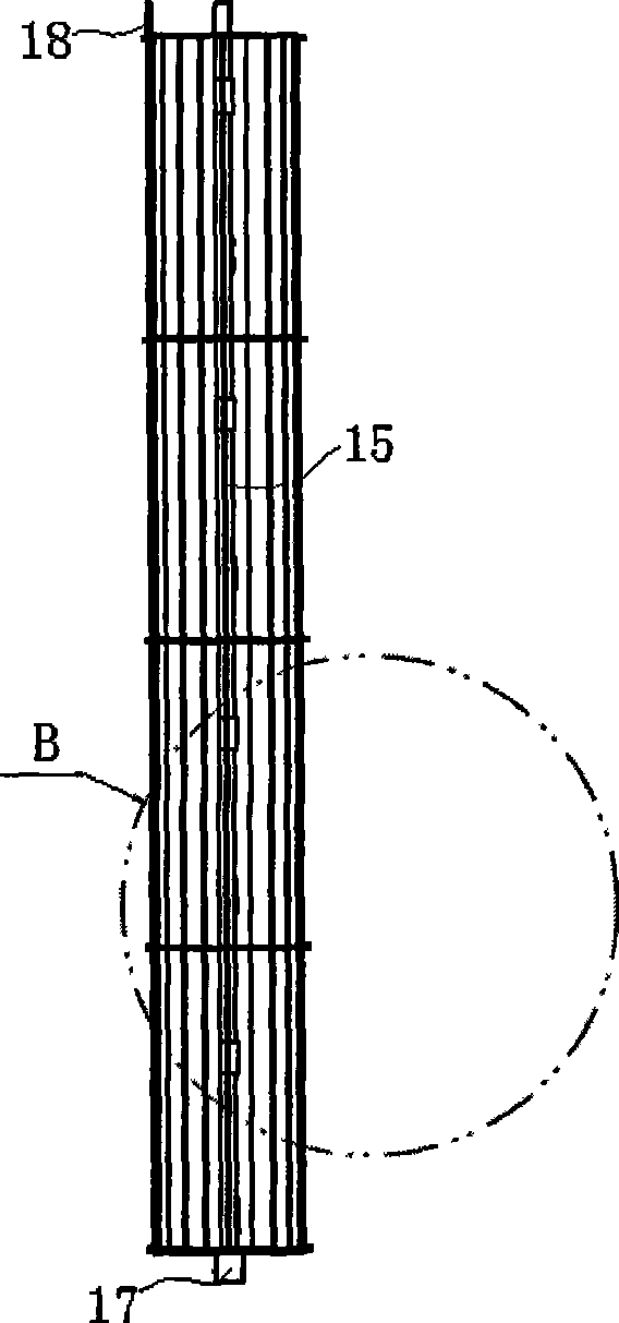
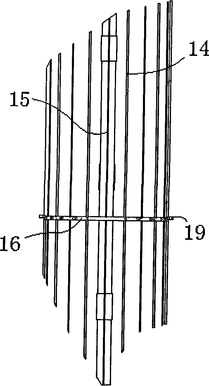
[0032] Such as Figure 1~4 Shown is a cylindrical tube-type sound-liquid comprehensive function co-processor that can treat waste water and waste gas. One end of the cylindrical tubular container is provided with a liquid material suction device, and the liquid material suction device is connected with the cylindrical tubular container through the lower flange 7 . The other end of the cylindrical tubular container is provided with a liquid material discharge device, and the liquid material discharge device is connected with the cylindrical tubular container through the upper flange 3 . The liquid material suction device is provided with a liquid material suction nozzle 9, and the liquid material suction nozzle 9 is provided with a liquid inlet valve 8 to control the feeding amount of the liquid. A liquid inlet pipe support frame 10 is arranged near the liquid material suction nozzle 9 to support and fix the liquid inlet pipe and the liquid material suction nozzle 9 . The liq...
Embodiment 2
[0036] Such as Figure 5 As shown, a plurality of ultrasonic transducers are arranged on the outer wall of the cylindrical tubular container 4 to form an ultrasonic liquid functional system. The irradiation direction of the ultrasonic transducer is perpendicular to the outer wall surface of the cylindrical tube container, and the ultrasonic transducer is connected with the ultrasonic controller 13 through wires. An ultrasonic transducer shield 5 is arranged on the outer wall surface of the cylindrical tubular container 4 to protect the ultrasonic transducer. The inner structure of the cylindrical tubular container 4 is the same as that of Embodiment 1, and a split-type functional load support network frame 12 is provided. The split-type functional load supporting net frame 12 is provided with a split-support catalytic functional net, an ultraviolet (UV) generator and a multi-porous ozone discharge tube. The difference is that one end of the cylindrical tubular container 4 is...
Embodiment 3
[0039] Such as Figure 6 ~ Figure 8 As shown, the external structure of the cylindrical tube container 4 is the same as that of Embodiment 1, and the internal structure is similar. The difference is that a conveyor belt 23 passes through the split-type functional load support network frame 12 inside the cylindrical tube container 4 . The conveyor belt 23 is arranged on the bottom bracket, and the bottom bracket is connected and fixed with the split-type functional load support network frame 12 . The bottom bracket supports and enables the conveyor belt 23 to run. One end of the conveyor belt 23 entering the cavity of the cylindrical tubular container 4 is provided with a feeding sealing vertical strip 24 . One end of the conveyer belt 23 outputting the cavity of the cylindrical tubular container 4 is provided with a discharge sealing vertical strip 25 .
[0040] In this embodiment, on the basis of the treatment of polluted gases in the above-mentioned embodiment 2, (UV+O 3...
PUM
 Abstract
Description
Claims
Application Information
 - R&D
- Intellectual Property
- Life Sciences
- Materials
- Tech Scout
- Unparalleled Data Quality
- Higher Quality Content
- 60% Fewer Hallucinations
Browse by: Latest US Patents, China's latest patents, Technical Efficacy Thesaurus, Application Domain, Technology Topic, Popular Technical Reports.
© 2025 PatSnap. All rights reserved.Legal|Privacy policy|Modern Slavery Act Transparency Statement|Sitemap|About US| Contact US: help@patsnap.com


