
High efficiency absorption heat pump and methods of use

An absorption heat pump and absorbent technology, applied in the field of heat pumps, can solve the problems of lack of high efficiency and achieve the effect of increasing energy efficiency

Inactive Publication Date: 2009-08-12
REXORCE THERMIONICS INC
View PDF13 Cites 28 Cited by
  • Summary
  • Abstract
  • Description
  • Claims
  • Application Information

AI Technical Summary

Problems solved by technology

[0018] High efficiency, a system with a coefficient of performance greater than 0.7, and an environmentally friendly and efficient absorption cycle using non-toxic, non-corrosive working fluids at positive operating pressures is lacking in the prior art

Method used


Image

  • High efficiency absorption heat pump and methods of use
  • High efficiency absorption heat pump and methods of use
  • High efficiency absorption heat pump and methods of use

Examples


example 1

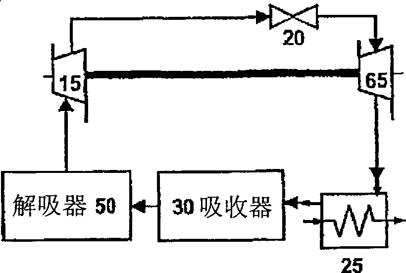
[0101] An absorption heat pump system in which the mode of operation for increasing the pressure from an initial pressure P0 to a second stage pressure P2 is selected from the group consisting of: (1) having a first adsorption or absorption stage with a pressure P1.sub .1, which contains a solid or liquid adsorbent; and a second adsorption or absorption stage having a pressure P2.sub.1, wherein the first stage adsorbent A1.sub.1 and the second stage liquid incompressible adsorbent A2. sub.1 combined and where P1.sub.1 is less than P2.sub.1, or (2) has a first stage of non-absorption compression stage containing a compressor or turbocharger where the first stage reduces the pressure from the initial pressure to P0.sub.2 is increased to the operating pressure P1.sub.2, and the second stage consists of an absorption stage containing solid or liquid adsorbent, where P1.sub.2 is smaller than P2.sub.2.

example 2

[0103] Example 1 further consists of a third stage to further increase the pressure, where the means of pressure increase comprises a non-absorption compression stage (ie, conventional compressor, turbocharger, etc.) or an absorption pumping stage.

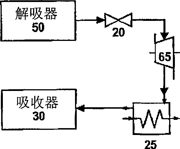
[0104] refer to Figure 12 , the desorbed refrigerant from the desorber 50, wherein the refrigerant is subsequently processed in at least one post-desorption process stage selected from reaction chemistry (including enzyme chemistry, fermentation chemistry), component extraction, The group consisting of supercritical combustion and combinations thereof in which the combined mechanical to electrical energy (E.sub.1) ratio required to increase the working fluid pressure to the operating pressure (P1) is reduced by compressing the compressible portion of the working fluid The combined mechanical and electrical energy (E.sub.2) required to increase the working fluid pressure to the operating pressure (P1) is at least 10% lower. This ...


PUM


Abstract

An energy conversion system including a high efficiency absorption heat pump cycle is disclosed using a high pressure stage, a supercritical cooling stage, and a mechanical energy extraction stage to provide a non-toxic combined heat, cooling, and energy system. Using the preferred carbon dioxide gas with partially miscible absorber fluids, including the preferred ionic liquids as the working fluid in the system, the present invention desorbs the CO.sub.2 from an absorbent and cools the gas in the supercritical state to deliver heat. The cooled CO.sub.2 gas is then expanded, preferably through an expansion device transforming the expansion energy into mechanical energy thereby providing cooling, heating temperature lift and electrical energy, and is returned to an absorber for further cycling. Strategic use of heat exchangers, preferably microchannel heat exchangers comprised of nanoscale powders and thermal-hydraulic compressor / pump can further increase the efficiency and performance of the system.

Description

technical field [0001] The present invention relates generally to heat pumps, and more particularly to high pressure absorption heat pumps using carbon dioxide and a low vapor pressure absorber as the circulating fluid. Background technique [0002] Heat pumps are well known in the art. A heat pump is simply a device used to deliver heat to or cool a system, while a refrigerator is a device used to remove heat from a system. Therefore, a chiller can be considered a type of heat pump. In this application, the invention is referred to as a heat pump, and it is understood that it can replace refrigerators, air conditioners, water heaters, combined heat and power systems (also station to simultaneously produce both electricity and useful heat) and combined heat, power and cooling (cogeneration system that additionally produces cooling) without changing the operation of the device. An inherent feature of a heat pump is to transfer / move thermal energy from a heat source to a he...

Claims


Application Information

Patent Timeline
Patent Type & Authority Applications(China)
IPC IPC(8): F25B9/00F25B15/00F25B13/00
CPCF01K23/02F25B30/04F01K3/02Y02E20/18C09K5/047F01K25/065Y02P20/10Y02P20/54
Inventor 迈克尔·H·古林
Owner REXORCE THERMIONICS INC
Learn More