The overall structure of the turning and milling compound machining center

A compound machining center and overall structure technology, applied in the direction of metal processing, metal processing equipment, manufacturing tools, etc., can solve problems such as no good, achieve the effect of improving efficiency, improving weight, keeping the environment clean and

Active Publication Date: 2012-02-22
通用技术集团沈阳机床有限责任公司
View PDF0 Cites 3 Cited by
  • Summary
  • Abstract
  • Description
  • Claims
  • Application Information

AI Technical Summary

Problems solved by technology

Even the machinery and equipment manufacturing industry has no good solutions to the above problems.

Method used


Image

  • The overall structure of the turning and milling compound machining center
  • The overall structure of the turning and milling compound machining center
  • The overall structure of the turning and milling compound machining center

Examples


Embodiment Construction

[0018] The overall structure of the turning-milling compound machining center is a special structure designed for machining the crankshaft of a medium-speed marine machine, and realizes the machining of each part of the crankshaft main journal and connecting rod journal before grinding on one machine tool. It is characterized in that it consists of the following five parts. :

[0019] 1. Single column, double side hanging feed mechanism

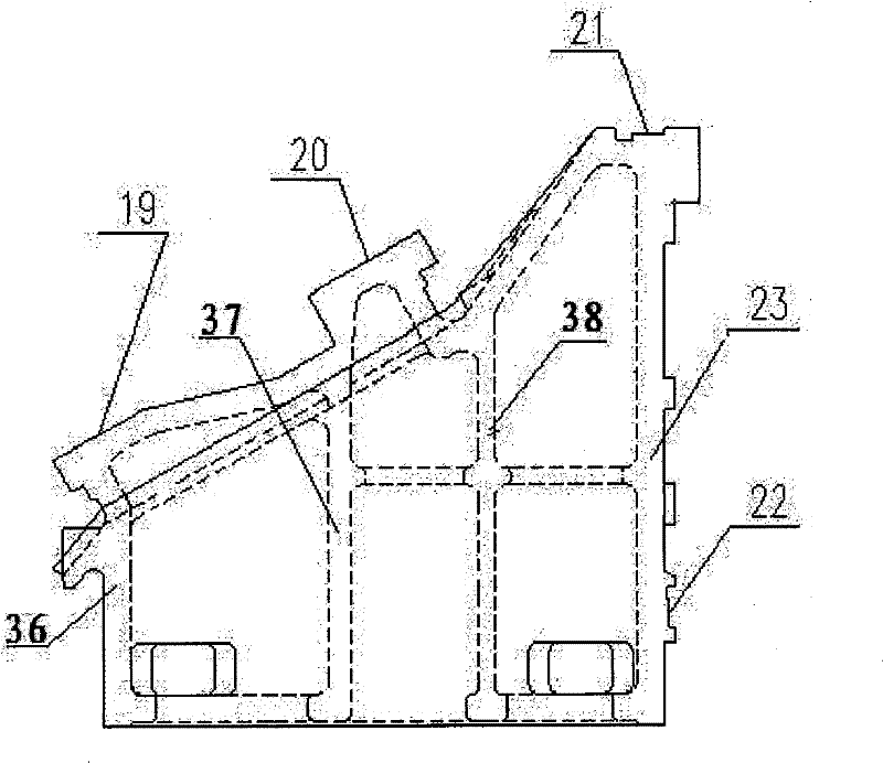
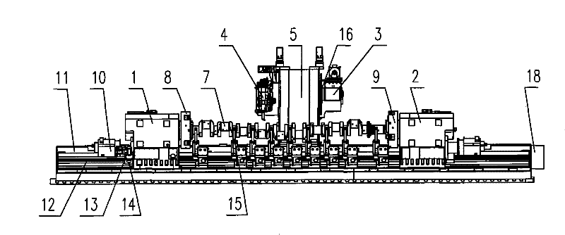
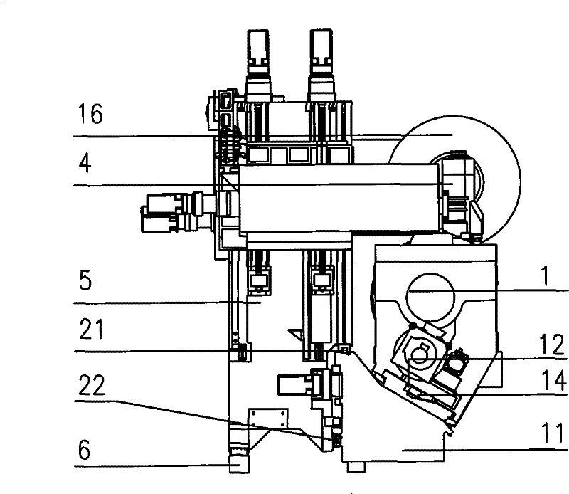
[0020] Such as figure 1 , figure 2 As shown, the single column 5 is located at the rear side of the bed, its lower front end is located in the horizontal load-bearing guide rail 21 and the auxiliary guide rail 22 on the bed, and the rear end runs in the auxiliary guide rail 6 on the ground. The stroke of the single column 5 is determined by the length of the workpiece to be processed. fixed, the left and right feeding mechanisms 4 and 3 are respectively hung on both sides of the single column 5, and the left feeding mechanism 4 is equipped...


PUM


Abstract

The overall structure of the turning-milling compound machining center is characterized by a single column and a feed box hung on both sides. The feed box on the left is equipped with a three-point cloth knife B-axis tool holder device. The B-axis tool post device is used for turning, milling, boring, deep hole drilling, tapping and other processes of crankshaft processing. The feed box hung on the right side can hold a large-sized milling cutter head for external milling of the crankshaft. Double spindle box and double Cf axis structure, the two spindle boxes can move along the Z axis on the bed, and the top of the right spindle box can be retracted. The machine tool is equipped with multiple hydraulic self-centering steady rests with high precision retention. The guide rail of the bed is at an inclination angle of 30° to the horizontal plane, and the upper plane of the bed is completely ground to ensure that there is no dead space for debris. The whole machine is fully protected. The inner cavity of the guide rail used for the operation of the single column of the bed is supported by double ribs, and the force of the two groups of corners is always maintained during the operation of the column. The front support bearing of the main shaft adopts imported large-diameter double-row cylindrical roller bearings. The present invention solves three problems. Only one clamping on a machine tool can complete the machining of the main journal of the crankshaft and each part of the connecting rod journal before grinding, and realize the high-precision and efficient machining of the crankshaft of the marine medium-speed engine. Great, full protection.

Description

technical field [0001] The invention relates to mechanical manufacturing equipment and the overall structural layout of a turning-milling compound machining center Background technique [0002] The crankshaft is known as the "heart" of the 10,000-ton wheel "heart" (engine), but China's shipbuilding industry has been lacking this "Chinese heart" for decades, and Chinese marine diesel engine manufacturers "ships wait for machines, machines wait for shafts" The situation has not been alleviated for several years, resulting in longer and longer delivery periods for Chinese shipbuilding companies, and has become a bottleneck restricting the development of China's shipbuilding industry. The material of the medium and low speed crankshaft for marine is cast iron or forged steel, and the shape is a long axis with multiple cranks. Since the rotary axis of the crank, that is, the connecting rod journal and the main journal are not concentric, the rotation diameter of the crank around ...

Claims


Application Information

Patent Timeline
Patent Type & Authority Patents(China)
IPC IPC(8): B23Q39/02
Inventor 李宪凯郭秀英李晓岩姜庆凯李晓峰白紫山盖立亚金明刚何峰刘春莉徐书友
Owner 通用技术集团沈阳机床有限责任公司
Why Eureka
Try Eureka