Super-precision trans-scale in-situ nanometer indentation marking test system

A nano-indentation and testing system technology, applied in the direction of testing material hardness, measuring devices, instruments, etc., can solve the problems of lack of in-depth research on the correlation between material deformation and damage mechanism, inability to test three-dimensional specimens, and complex testing.

Active Publication Date: 2011-05-18
JILIN UNIV
View PDF0 Cites 2 Cited by
  • Summary
  • Abstract
  • Description
  • Claims
  • Application Information

AI Technical Summary

Problems solved by technology

[0007] Regarding ex-situ mechanical testing techniques such as nanoindentation and nanoscratch, A.M.Minor and others from the University of California, Berkeley and Lawrence-Berkeley National Laboratory pointed out their shortcomings: due to the inability to use scanning electron microscopy and transmission electron microscopy High-resolution in-situ monitoring is carried out under (SEM, TEM), so it is impossible to study the correlation between deformation, damage, load and material performance parameters; There is a lack of in-depth research on the correlation law between performance parameters, which is urgently needed in the design and manufacture of tiny components
Limited to the technical level at that time, the device had a large structure and insufficient positioning accuracy; it could only monitor the deformation behavior and damage of the material, but could not test the mechanical parameters; Scale deformation and damage mechanism issues become possible
Since then, the researchers have pushed the doped diamond tool head through the piezoelectric drive mechanism to realize the in-situ nano-indentation test in the vacuum chamber of the electron microscope, and conducted experiments on single crystal silicon and other materials, and monitored the indentation load of the material. The whole process of deformation and internal defects, but their work also has some deficiencies: ①The amount of deformation (or displacement) is obtained through electron microscope observation, ②The loading force is obtained by the voltage applied to the piezoelectric element and the amount of deformation It is obtained through the conversion of the relationship; thus resulting in complex testing, too many offline operations, and reducing the credibility of the test results
But this research also has some deficiencies: ① there is an insurmountable backlash phenomenon in the driving mechanism (the backlash amplitude reaches 30-100nm); ② the loading resolution is insufficient (100mN), ③ tangential scratches cannot be detected force
At present, the commercial products of in-situ nanomechanical testing are only produced by Hysitron Company of the United States, which are very expensive and are also embargoed to my country; Parts must also be manufactured through complex and cumbersome processes such as "mask, corrosion, deposition", etc., and it is impossible to test three-dimensional specimens with feature sizes above millimeters
Due to factors such as scale effects in the test, it is not credible to use the test results of extremely small specimens to evaluate the comprehensive mechanical properties of larger-sized three-dimensional specimens

Method used


Image

  • Super-precision trans-scale in-situ nanometer indentation marking test system
  • Super-precision trans-scale in-situ nanometer indentation marking test system
  • Super-precision trans-scale in-situ nanometer indentation marking test system

Examples


Embodiment Construction

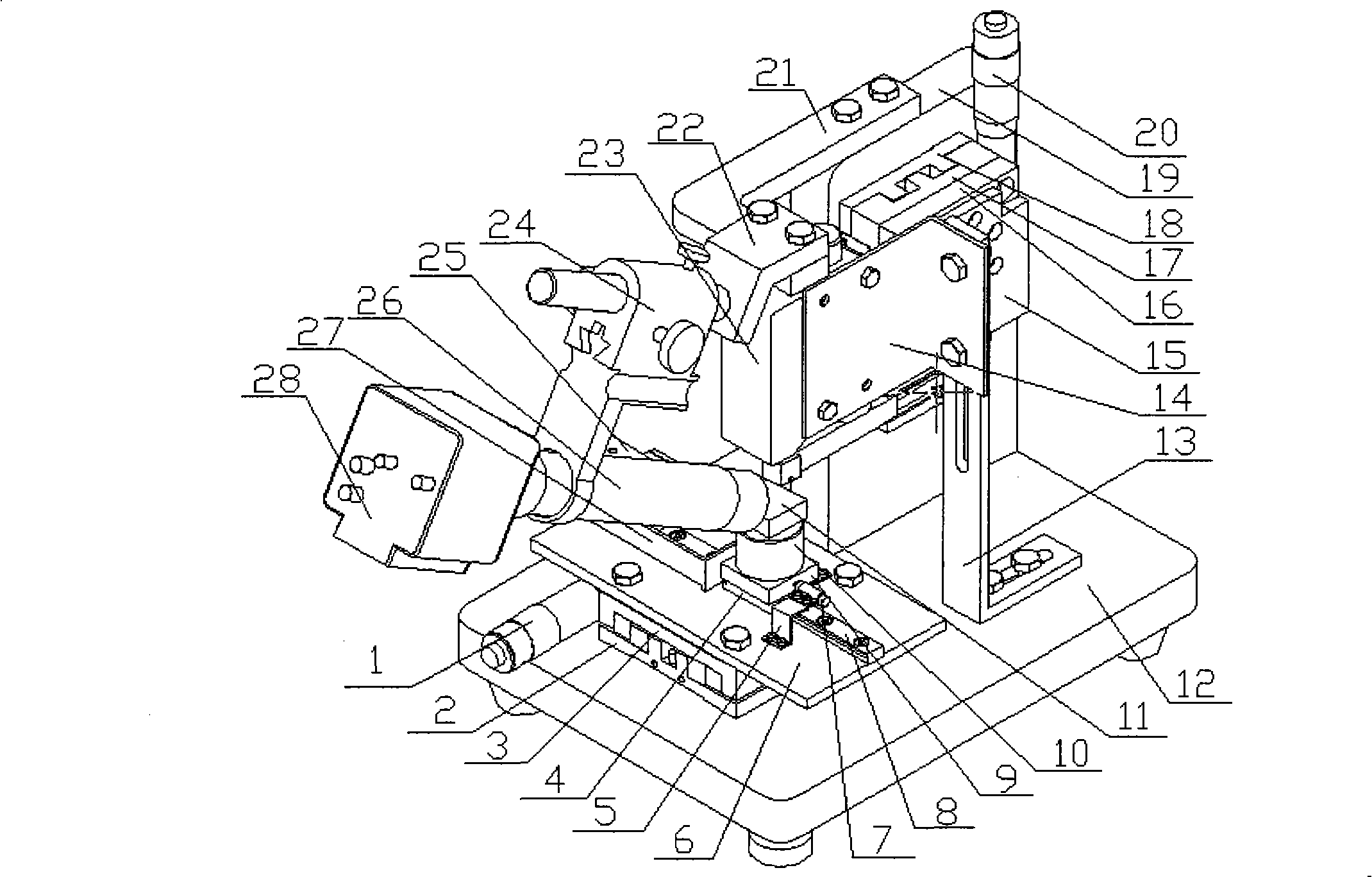
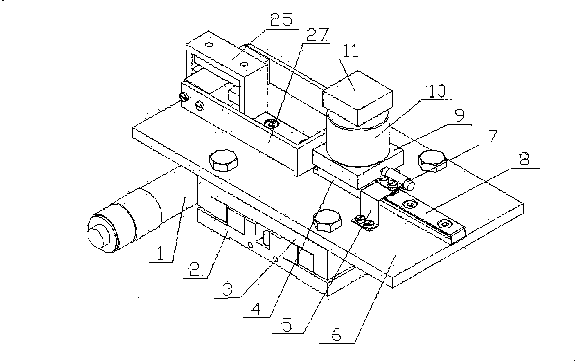
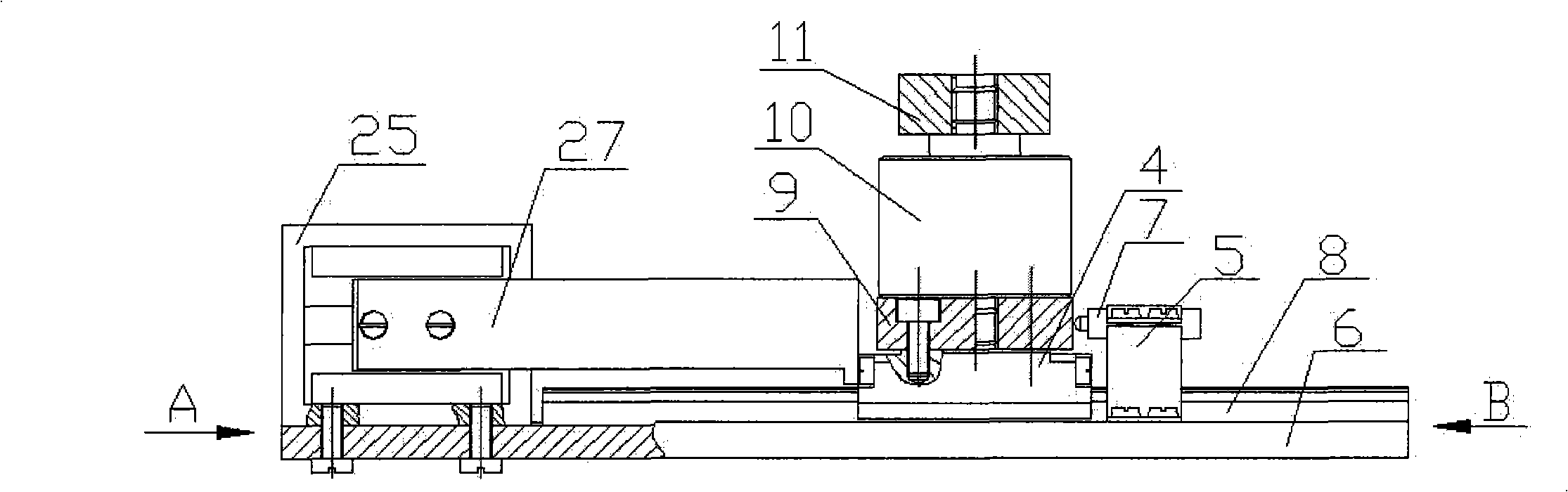
[0035] The detailed content and specific implementation of the present invention will be further described below in conjunction with the embodiments shown in the drawings.

[0036] A high-performance comprehensive precision experimental system of the present invention. The stage with precise positioning of X and Y axes is horizontally arranged on the base, and the precision micro-moving table is used as the drive in the Y-axis direction, and the sliding table of the micro-moving table is driven. The X-axis precision positioning mechanism on the sliding table, the micro-motion table has a large load-bearing capacity, stable operation and easy control. The X-axis precision positioning mechanism is driven by a voice coil motor, and a precision displacement sensor is used to detect the micro-displacement. By feeding back the micro-displacement signal to the control power supply of the voice coil motor, closed-loop control can be realized, and precise positioning in the X-axis directio...


PUM


Abstract

The invention relates to a super-precision trans-scale in-situ nanometer indentation marking test system which integrates driving, loading, detecting and micro-nanometer dynamic performance tests, supThe invention relates to a super-precision trans-scale in-situ nanometer indentation marking test system which integrates driving, loading, detecting and micro-nanometer dynamic performance tests, super-precision marking processing and in-situ observation into a whole. The system mainly comprises an objective table, a regulation mechanism, a detection unit, a precise pressed-into driving unit, a der-precision marking processing and in-situ observation into a whole. The system mainly comprises an objective table, a regulation mechanism, a detection unit, a precise pressed-into driving unit, a detection unit of load signals and displacement signals and a high-resolution digital microscopic imaging system, wherein the objective table is precisely positioned along the directions of the X axisetection unit of load signals and displacement signals and a high-resolution digital microscopic imaging system, wherein the objective table is precisely positioned along the directions of the X axisand the Y axis; the regulation mechanism and the precise pressed-into driving unit are in the direction of the Z axis and are assembled on a base; the high-resolution digital microscopic imaging systeand the Y axis; the regulation mechanism and the precise pressed-into driving unit are in the direction of the Z axis and are assembled on a base; the high-resolution digital microscopic imaging system is used for observing the deforming and damaging conditions of the material in the storing and testing process; the objective table as well as the regulation mechanism and the precise pressed-into dm is used for observing the deforming and damaging conditions of the material in the storing and testing process; the objective table as well as the regulation mechanism and the precise pressed-into driving unit in the direction of the Z axis are assembled on a base; the high-resolution digital microscopic imaging system is arranged on the objective table; a precise dynamic sensor detecting the prriving unit in the direction of the Z axis are assembled on a base; the high-resolution digital microscopic imaging system is arranged on the objective table; a precise dynamic sensor detecting the pressure of a diamond tool head pressed into a material and a sensor I detecting the precise displacement of the objective table in the directions of the X axis and the Y axis are arranged on the objectessure of a diamond tool head pressed into a material and a sensor I detecting the precise displacement of the objective table in the directions of the X axis and the Y axis are arranged on the objective table; and a sensor II used for detecting the precise displacement of a diamond tool head in the direction of the Z axis of pressed-into depth is arranged on the base by a support I.ive table; and a sensor II used for detecting the precise displacement of a diamond tool head in the direction of the Z axis of pressed-into depth is arranged on the base by a support I.

Description

Technical field [0001] The invention relates to a high-performance comprehensive precision experimental test system that integrates driving, loading, detection, micro-nano mechanical performance testing, ultra-precision scribing processing and in-situ observation, in particular to the micromechanics of various test pieces or materials In the performance test, the nano-pressure / scratch experiment, in-situ nano-pressure / scratch experiment, and micro-nano-level in-situ diamond scribing processing devices are precision scientific instruments integrating optical and mechanical integration. Precision instruments are the cornerstone and important guarantee of scientific and technological innovation and economic and social development. The present invention is a special testing instrument used to measure the micromechanical performance parameters of various specimens or materials, and can be used in high-resolution digital microscopy imaging systems. Under real-time monitoring, study th...

Claims


Application Information

Patent Timeline
Patent Type & Authority Patents(China)
IPC IPC(8): G01B11/16G01N3/46
Inventor 赵宏伟黄虎邓金强赵宏健
Owner JILIN UNIV
Why Eureka
Try Eureka