Thermosynthesis device

A technology of forming and heating gas, which is applied in the field of thermosynthesis, can solve problems such as interruption, and achieve the effect of increasing acetylene yield and conversion efficiency

Inactive Publication Date: 2009-09-09
BECHTEL BWXT IDAHO
View PDF1 Cites 5 Cited by
  • Summary
  • Abstract
  • Description
  • Claims
  • Application Information

AI Technical Summary

Problems solved by technology

[0025] None of the above mentioned patents clearly mention energy consumption
An attempt was made to develop an in...

Method used


Image

  • Thermosynthesis device
  • Thermosynthesis device
  • Thermosynthesis device

Examples


Embodiment 1

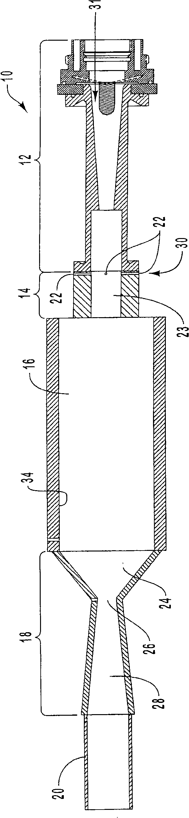
[0117] In this example, the results of tests carried out in the presence of a convergent-divergent nozzle are given. The change of conversion efficiency with methane injection flow rate is shown in Figure 5 middle. In the process of obtaining this set of data, the power into the plasma was kept constant at 60kW, and the flow rate of the plasma gas was constant at 160slm of Ar and 100slm of H 2 . The measured reactor pressure was relatively constant and varied between about 670-730 Torr depending on the methane injection flow rate. The conversion of methane is essentially complete, ie, the conversion efficiency is 100% at feed rates of methane up to about 100 slm. At feed rates above 100 slm, the conversion efficiency begins to drop and drops below about 95% at feed rates of about 120 slm. The estimated bulk gas temperature in the reactor and the corresponding residence time in the reactor are plotted in Image 6 middle. This estimate was obtained from the measured syste...

Embodiment 2

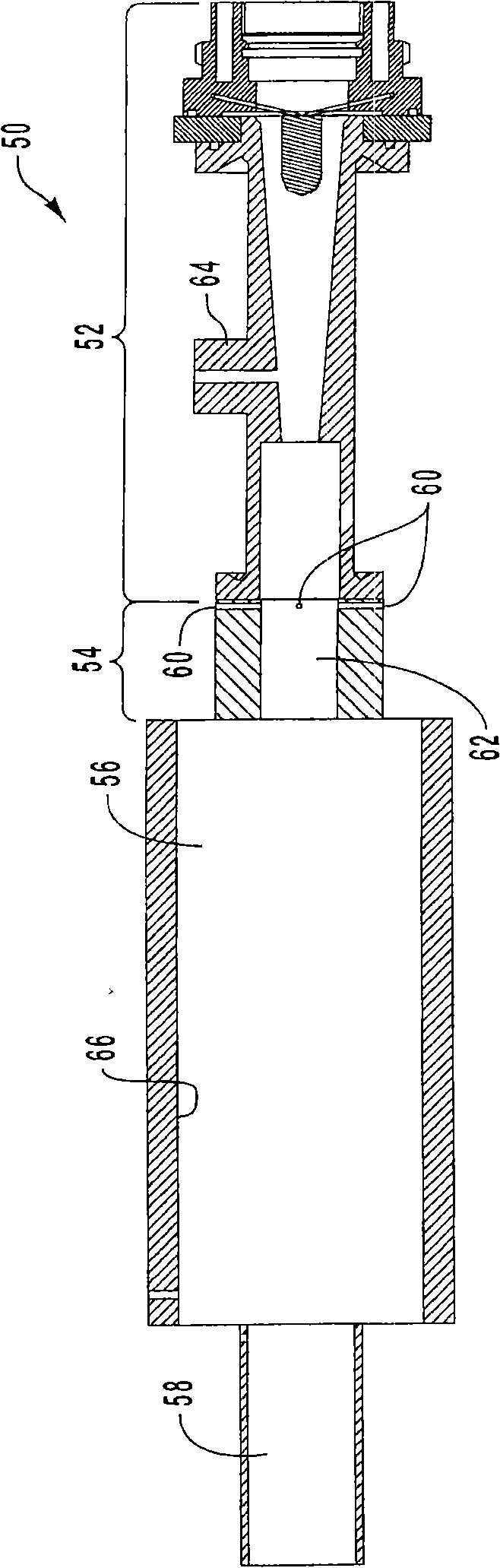
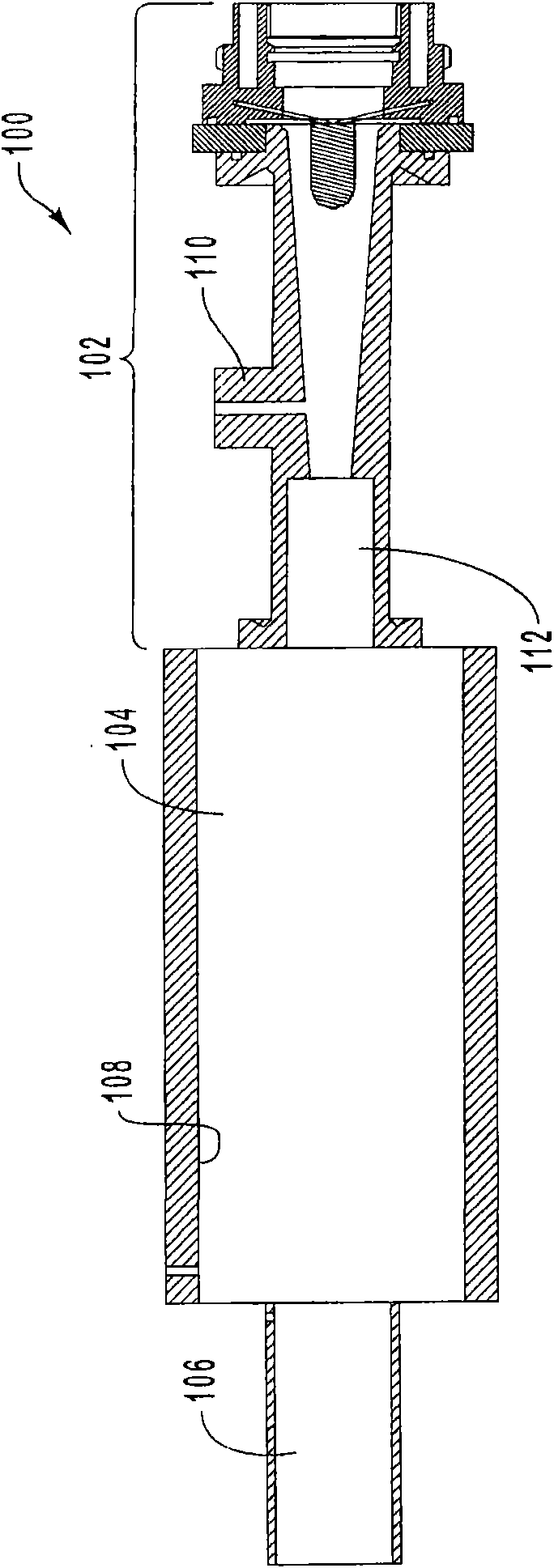
[0129] Presented in this example are test results without using a convergent-divergent nozzle. The resulting yield conversion efficiency (-100% vs. 70%) and selectivity (95% vs. 51%) of this process appears to be slightly better than the original Huels process. This could be due to better mixing, uniform temperature or faster quenching. The analysis of the Huels product stream is summarized in Table 2, along with the lab-scale results.

[0130] To evaluate the effect of rapid pneumatic quenching, the same series of experiments as described in Example 1 was carried out, but without the use of a convergent-divergent nozzle. During these tests, the system pressure was maintained at 700-900 Torr, approximately the same as the reactor pressure in the Example 1 series of tests. Results for conversion efficiencies, yields and normalized yields are summarized in Figure 12-14 middle. The yields of other hydrocarbons are summarized in Figure 15 middle.

[0131] The yield and con...

Embodiment 3

[0135] Comprehensive data for one test are given in Tables 3-5 below. This test was performed without a convergent-divergent nozzle. Table 3 presents a summary of flows, powers, measured flare thermal efficiencies, nozzle geometries, and reactor and outlet pressures.

[0136] table 3

[0137] Test SEPT13A-4P


PUM


Abstract

A device for thermal transformation of one or a plurality of reagents into at least one needed product comprises an axial reactor, a torch part and an injector part, wherein the axial reactor comprises an inlet end, an outlet end, a reaction zone arranged between the inlet end and the outlet end, and a reactor inlet arranged on the inlet end; the torch part is constructed to generate thermal gas; and the injector part is inserted between the torch part and the axial reactor and comprises a thermal gas inlet and at least one reagent inlet.

Description

[0001] This application is a divisional application of the invention patent application with the application number "02146936.9" and the invention title "thermal synthesis device and method" submitted by the applicant on October 25, 2002. technical field [0002] The present invention generally relates to a thermal synthesis process. In particular, the present invention relates to methods and apparatus for the thermal conversion of reactants in a thermodynamically stable high temperature gas stream to a desired end product, such as a gas or ultrafine solid particles. Background technique [0003] Natural gas, of which methane is the predominant hydrocarbon, is cheap and an underutilized energy source in the United States. Large deposits of natural gas are known to exist in remote areas of the continental United States, but this energy source cannot be economically and safely transported from these areas. The conversion of natural gas into higher-value hydrocarbons has been ...

Claims


Application Information

Patent Timeline
IPC IPC(8): B01J19/08B01J19/26B01J12/02C22B34/12C07C2/80C07C11/24
Inventor J·R·芬克B·A·德特林
Owner BECHTEL BWXT IDAHO
Why Eureka
Try Eureka