High-pressure dynamic internal gear flowmeter

An internal gear and flow meter technology, applied in the field of dynamic flow test of fluid transmission, can solve the problems of difficult dynamic flow measurement of hydraulic system, difficult high-pressure dynamic flow measurement, large moment of inertia, etc. Simple, large measuring range effect

Inactive Publication Date: 2009-09-09
ANHUI UNIV OF SCI & TECH
View PDF2 Cites 4 Cited by
  • Summary
  • Abstract
  • Description
  • Claims
  • Application Information

AI Technical Summary

Problems solved by technology

Flowmeters are one of the few instruments that are much more difficult to use than to manufacture. In the laboratory they can be extremely accurate, but in the field, once conditions change, it is all for naught.
Invention patent JP2306122 "Positive displacement flowmeter" and invention patent 200610049716.6 "High pressure bidirectional oval gear flowmeter" are both based on oval gears as the research object. There is no flow pulsation that the oval gear flowmeter itself may bring to the measured system. Considering that it is difficult to measure high-pressure dynamic flow
The new utility patent ZL200620006026.8 "balanced multi-gear high-pressure dynamic flowmeter" is difficult to use because of its complex structure, many rotating parts, large moment of inertia, and the participation of external meshing gear pairs. For the measurement of dynamic flow in hydraulic systems

Method used


Image

  • High-pressure dynamic internal gear flowmeter
  • High-pressure dynamic internal gear flowmeter
  • High-pressure dynamic internal gear flowmeter

Examples


Embodiment Construction

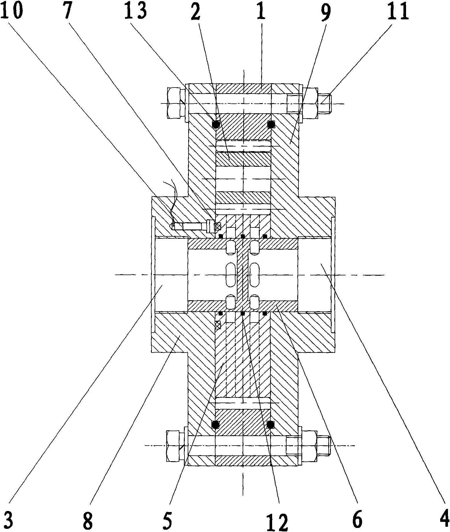
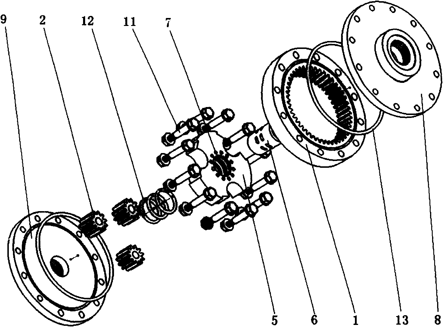
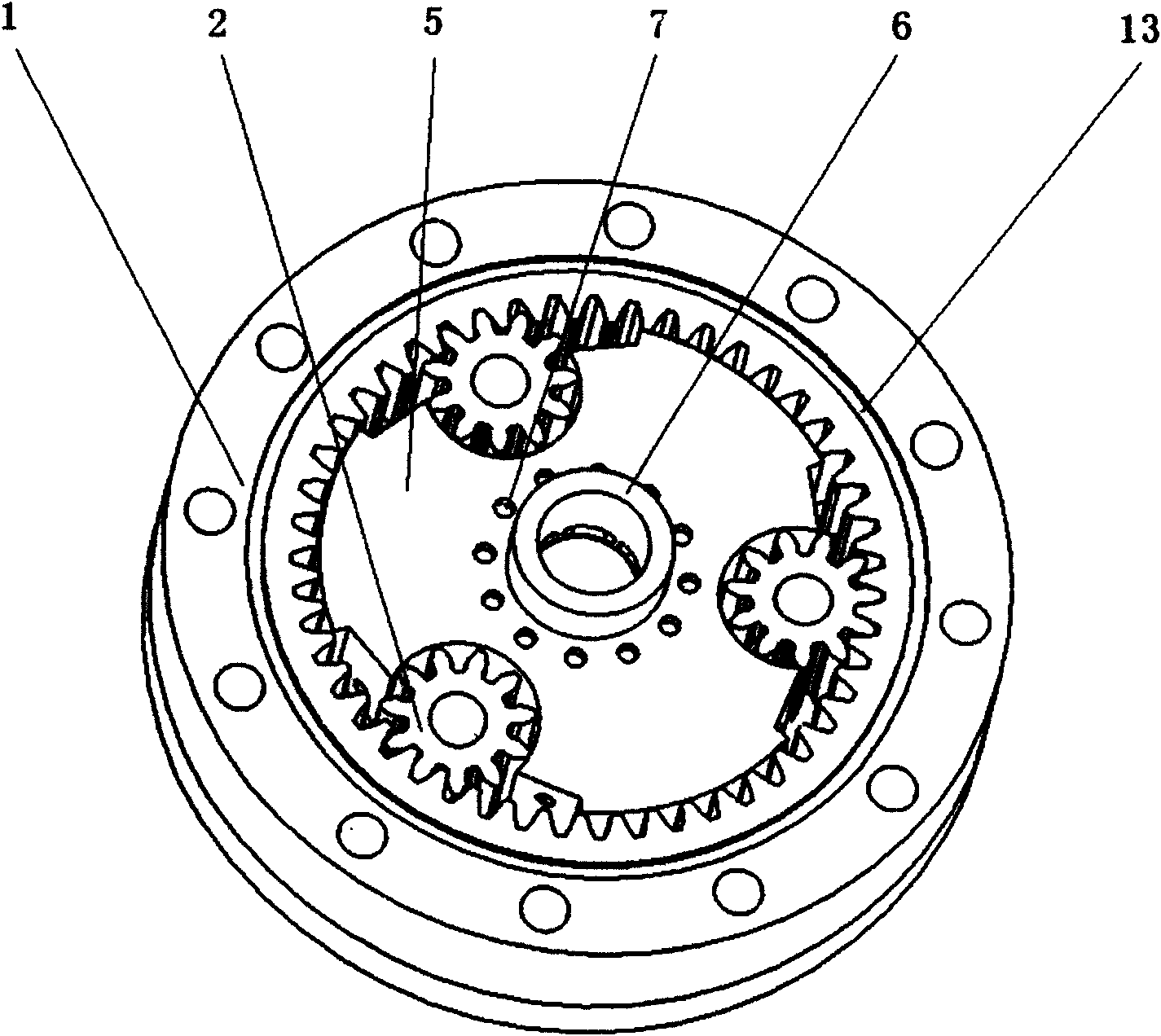
[0019] like figure 1 , 2 , 3, 4, 5, 6, and 7, three pinion gears (2) are evenly distributed in the fixed internal gear (1), and together with the cage (5), the distribution shaft (6 ) support. The front casing (8), the rear casing (9), together with the internal gear (1), three pinion gears (2), the cage (5) and the flow distribution shaft (6) form three airtight oil inlets ( 3), three oil outlets (4), a liquid inlet is arranged on the front housing (8), and a liquid outlet is arranged on the rear housing (9). Internal gear (1) and figure 2 The front housing (8) and the rear housing (9) are fixed together, the cage (5) is equipped with a uniformly distributed magnet (7) for speed measurement, and the front housing (8) is equipped with a gear speed sensor (10) , the front housing (8), the rear housing (9) and the internal gear (1) are sealed with O-rings (13), connected with bolts (11), and the cage (5) is provided with a cage for oil inlet The mouth ring groove (14) and ...


PUM


Abstract

The invention discloses a high-temperature dynamic internal gear flowmeter. An internal gear and a shell are fixed together, and the number of small pinions can be 2 to 4. Three pinions are taken as instance for description as follows: a liquid to be measured passes through a pintle valve and a retainer through an oil inlet to enter three oil inlet cavities of the internal gear; the three pinions and the retainer are pushed to move so as to bring the oil into three oil outlet cavities of the internal gear; the oil passes through the retainer and the pintle valve to reach an oil outlet; a flow rate signal of the liquid to be measured is converted to a rotating speed signal of the retainer, and the rotating speed signal is converted to an electric signal by a rotary transducer; and the dynamic flow rate of a system to be measured is determined by the measured electric signal finally. The pinions and the retainer are made of light wear resistant materials and have small moment of inertia; the tooth number of the internal gear is a non-three interger multiple, and the flow rate realizes dislocation and superposition; the flow pulsation of the flowmeter is very small, and the flow quality is obviously improved; and because the flowmeter belongs to a volumetric flowmeter, the flowmeter is not influenced by testing environmental conditions, can accurately measure the high-pressure flow rate of a hydraulic system, has the advantages of wide measuring range, high precision, good reliability and the like, and can be widely used for measuring the flow rate of high-pressure hydraulic systems in the industries such as chemical engineering, coal mine, metallurgy and the like.

Description

technical field [0001] The high-pressure dynamic internal gear flowmeter is suitable for systems that use mineral oil, emulsion or water as the working medium. It is a high-pressure flowmeter that can reliably measure the flow of high-pressure hydraulic systems. It belongs to the field of dynamic flow testing of fluid transmission. Background technique [0002] For the flow measurement of high-pressure hydraulic systems, there are no products that have been formed in China at present. Only in the laboratories of some research institutions and colleges, the flow can be accurately measured by indirect flow measurement under laboratory conditions. However, if the experiment If conditions change, such as fluid viscosity, temperature, flow velocity, pulsation, pressure, flow state, etc., it is difficult to accurately measure the flow rate of the high-pressure hydraulic system. A flow meter is a meter whose performance is strongly dependent on the conditions of use. Flowmeters ar...

Claims


Application Information

Patent Timeline
Patent Type & Authority Applications(China)
IPC IPC(8): G01F1/05
Inventor 张军
Owner ANHUI UNIV OF SCI & TECH
Why Eureka
Try Eureka