Ultraviolet irradiation set and ultraviolet irradiation processing unit

A technology of irradiation device and ultraviolet rays, which is applied in the direction of original parts for photomechanical processing, nonlinear optics, and photoplate making process of patterned surface, etc., which can solve the problems of high cost, reduced production volume, and reduced transportation speed of workpiece W , to achieve the effect of reducing cost, increasing production capacity and reducing volume

Active Publication Date: 2009-09-09
USHIO DENKI KK
View PDF1 Cites 10 Cited by
  • Summary
  • Abstract
  • Description
  • Claims
  • Application Information

AI Technical Summary

Problems solved by technology

However, if Figure 13 As shown, in the conventional ultraviolet irradiation treatment device, a plurality of excimer lamps J adjacent to each other are arranged at predetermined intervals, so the internal volume of the open lampshade A has to be increased.
Therefore, the ultraviolet irradiation space X from the surroundings of the plurality of excimer lamps J arranged inside the open lampshade A to the workpiece W is filled with the flow of inert gas, and must pass through the gas supply duct D and the gas supply port CA. There is a problem that a large amount of inert gas is supplied and the cost becomes high
In addition, since it takes a long time to fill the inert gas around the excimer lamp J with the inert gas through the fine holes of the gas diffusion plate B, the transport speed of the workpiece W has to be reduced, which may lower the throughput. such problem

Method used


Image

  • Ultraviolet irradiation set and ultraviolet irradiation processing unit
  • Ultraviolet irradiation set and ultraviolet irradiation processing unit
  • Ultraviolet irradiation set and ultraviolet irradiation processing unit

Examples


no. 1 Embodiment approach

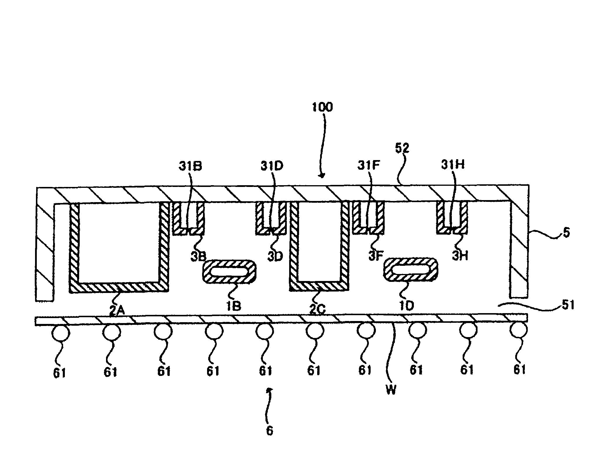
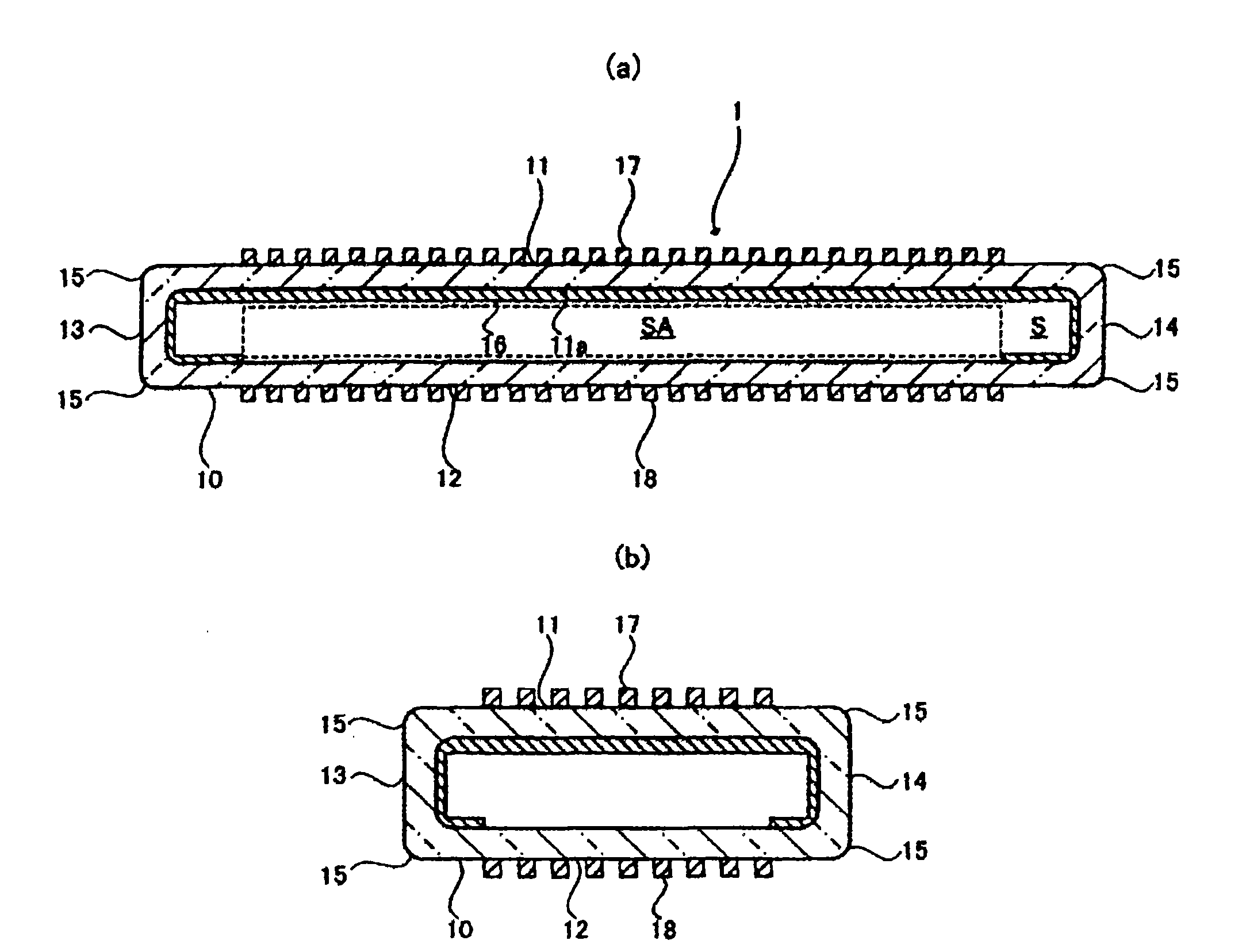
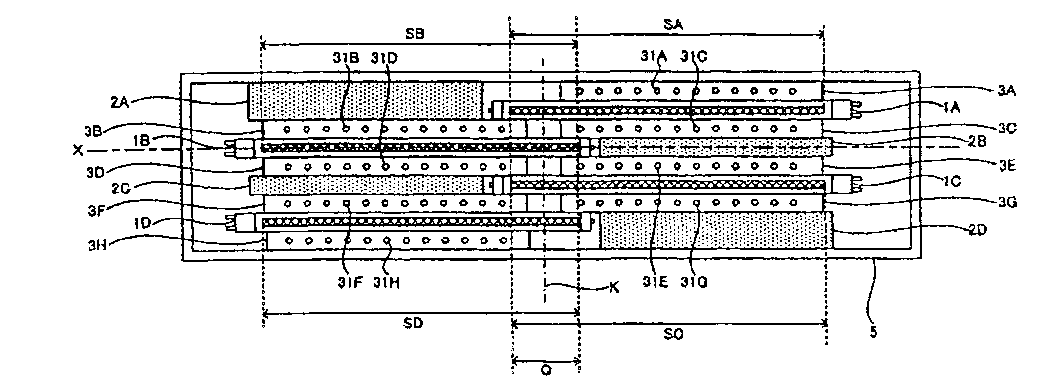
[0057] Hereinafter, for the first embodiment of the ultraviolet irradiation device of the present invention, use Figure 1 to Figure 5 Be explained. figure 1 It is a sectional view showing the structure of the ultraviolet irradiation device of this invention. figure 2 It is a sectional view showing the structure of an excimer lamp. figure 2 (a) shows a cross-sectional view of the excimer lamp cut in the direction of the central axis. figure 2 (b) is a cross-sectional view showing the excimer lamp cut in a direction perpendicular to the central axis. image 3 It is a figure which shows the ultraviolet irradiation apparatus of this invention seeing from a vertical direction. Figure 4 It is a diagram conceptually showing the arrangement of an excimer lamp, a space enclosure, and an object to be processed. Figure 5 It is a figure which shows the structure of a space enclosure.

[0058] The ultraviolet irradiation device 100 is inside a lampshade 5 made of a metal casing...

no. 2 Embodiment approach

[0078] Hereinafter, for the second embodiment of the ultraviolet irradiation device, use Figure 7 to Figure 8 Be explained. This embodiment is preferably applied when the overall length in the direction perpendicular to the conveyance direction of the object to be processed is short. Figure 7 It is a sectional view which shows the structure of 2nd Embodiment of the ultraviolet irradiation apparatus of this invention. Figure 8 Yes means viewing from a vertical direction Figure 7 The diagram when the UV irradiation device is shown. exist Figure 7 , Figure 8 in, with Figure 1 to Figure 5 The same parts are given as Figure 1 to Figure 5 same symbol.

[0079] In the ultraviolet ray irradiation device 200, a plurality of excimer lamps 1A-1C are arranged in parallel in isolation from each other inside the lampshade 5 formed of a metal casing having an opening on the lower side in the vertical direction. There are gas supply pipes 3A to 3F for supplying inert gas such ...

no. 3 Embodiment approach

[0085] Hereinafter, for the third embodiment of the ultraviolet irradiation device of the present invention, use Figure 9 to Figure 11 Be explained. Figure 9 is a cross-sectional view showing the ultraviolet irradiation device. Figure 10 It is a perspective view showing a part of the ultraviolet irradiation device viewed obliquely from above. Figure 9 , Figure 10 in, with Figure 1 to Figure 5 Common parts given with Figure 1 to Figure 5 same symbol. Figure 11 It is a figure for demonstrating the structure of the support body of an excimer lamp. Figure 12 It is a perspective view for explaining the intermittent lighting.

[0086] In the ultraviolet irradiation device 300, the specifications of the lampshade 5 are unified into multiple types. Regardless of the size of the object W to be processed, when processing a variety of objects W to be processed, the lampshade 5 is generally used in common. The number of excimer lamps 1 housed in the lampshade 5 is determin...


PUM


Abstract

The invention provides an ultraviolet irradiation set which can fill the non-active gas rapidly around the quasi-molecule lamp and comprises: a plurality of quasi-molecule lamps enclosed with the discharging gas in a sealed space formed in a discharging container and forming a pair of electrodes on the outer surface of the capacitor isolated by the sealed space; a lampshade surrounding the plurality of quasi-molecule lamps, opening at one direction of the vertical direction and a gas supply mechanism for supplying the non-active gas to the interior of the lampshade. The ultraviolet irradiation set is characterized in that in the lampshade the space shielding body is disposed in a space out of the space of the quasi-molecule lamp.

Description

technical field [0001] The present invention relates to an ultraviolet irradiation treatment device, and more particularly to an ultraviolet irradiation device and an ultraviolet irradiation treatment device using an excimer lamp used for cleaning a semiconductor substrate or a liquid crystal substrate in a manufacturing process of a semiconductor substrate or a liquid crystal substrate, etc. . Background technique [0002] In recent manufacturing processes of semiconductor substrates or liquid crystal substrates, as a method of removing dirt such as organic compounds adhering to the surface of a silicon wafer of a semiconductor substrate or a glass substrate of a liquid crystal substrate, a dry cleaning method using ultraviolet rays has been adopted. widely used. In particular, in the cleaning method of ozone or active oxygen using vacuum ultraviolet light radiated from an excimer lamp, various cleaning devices that are more efficient and cleaned in a short time are propos...

Claims


Application Information

Patent Timeline
Patent Type & Authority Applications(China)
IPC IPC(8): H01L21/00H01L21/268B08B7/00H01L21/312G03F7/26B01J19/12G02F1/13G03F1/82H01J65/00H01L21/304
CPCB08B7/0035H01L21/67034
Inventor 远藤真一菅敏幸石原肇
Owner USHIO DENKI KK
Why Eureka
Try Eureka