Satellite-borne data transmission transmitter using microwave direct modulation technique

A modulation technology and spaceborne data transmission technology, applied in the field of spaceborne data transmission transmitters, can solve the problems of difficult to achieve light weight, miniaturization, large assembly and disassembly workload, and long production cycle, and achieve excellent electromagnetic compatibility performance, The effect of good shielding isolation characteristics and convenient debugging

Inactive Publication Date: 2009-09-23
ACAD OF OPTO ELECTRONICS CHINESE ACAD OF SCI
View PDF0 Cites 10 Cited by
  • Summary
  • Abstract
  • Description
  • Claims
  • Application Information

AI Technical Summary

Problems solved by technology

At the same time, in order to meet the electromagnetic compatibility performance of the digital transmission transmitter, it is required that the connection between the multi-layers is tight and there is no leakage. Therefore, the processing accuracy of the chassis connection structure is high, the processing technology is complicated, and the production cycle is long.
In addition, the multi-layer structure has many assembly and disassembly procedures and complex connections, especially after the whole machine is assembled, such as debugging a certain layer of local circuits, it is necessary to disassemble all the structures above this layer, which requires a large amount

Method used


Image

  • Satellite-borne data transmission transmitter using microwave direct modulation technique
  • Satellite-borne data transmission transmitter using microwave direct modulation technique
  • Satellite-borne data transmission transmitter using microwave direct modulation technique

Examples


Embodiment Construction

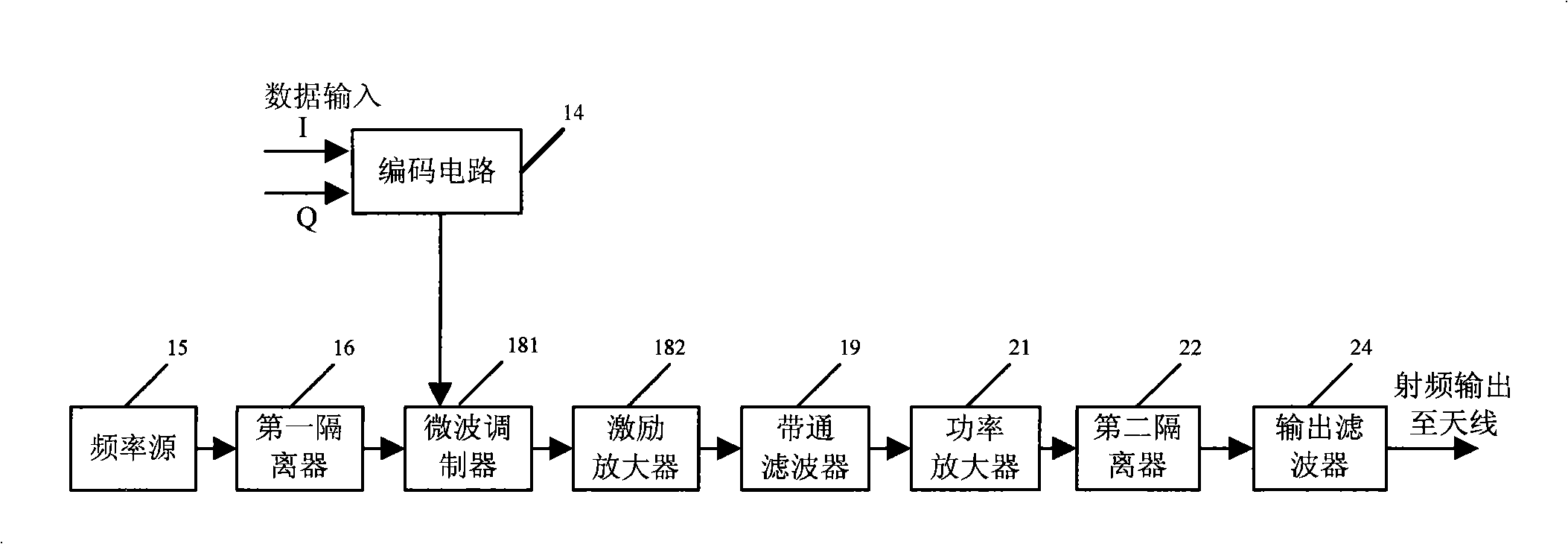
[0024] like figure 1 Shown is the functional composition and working principle diagram of the spaceborne digital transmission transmitter of the present invention, including a power supply circuit, an encoding circuit 14, a frequency source 15, a first isolator 16, a microwave modulator 181, an excitation amplifier 182, and a bandpass filter 19, solid-state power amplifier 21, second isolator 22, output filter 24, and connectors and connecting cables between each part. The working principle of the digital transmission transmitter is as follows: the input baseband digital signal is sent to the data input end of the microwave modulator 181 after being shaped by the coding circuit 14 and encoded by DQPSK, and the radio frequency carrier signal generated by the frequency source 15 is isolated by the first isolator 16 Then it is directly sent to the radio frequency input end of the microwave modulator 181. Inside the microwave modulator 181, the baseband digital signal after shapi...


PUM


Abstract

The invention provides a satellite-borne data transmission transmitter using a microwave direct modulation technique. A shell is a cuboid structure, the upper and lower surfaces thereof are both provided with sunken shielding grooves, and outer side of the upper surface of the shell is anticlockwise provided with a frequency source, a first isolator, a microwave modulator, an exciting amplifier, a band-pass filter, a solid state power amplifier, and a second isolator in sequence. A coding circuit is located in a single shielding groove in the centre of the upper surface of the shell, the frequency source and the first isolator are arranged in the same shielding groove, the microwave modulator and the exciting amplifier are arranged in the same shielding groove, and the shielding covers of the three shielding groove are top cover plates of a first machine case. A power amplifier and the second isolator are arranged in the same shielding groove, the shielding cover is the top cover plate of a second machine case, and an output filter is located above the solid state power amplifier and fixed above the top cover plate of the second machine case. A 38-core electric connector is mounted on the side wall of the shell. A power supply circuit is arranged on the lower surface of the shell. The data transmission transmitter in the invention has small volume, light weight and strong electromagnetic compatibility, and is conveniently disassembled.

Description

technical field [0001] The invention belongs to the field of microwave communication, and relates to a spaceborne digital transmission transmitter. Background technique [0002] With the development of satellite communication technology, the requirements for the development of space-borne communication equipment are also continuously increasing, such as micro-satellites or deep-space communication equipment, the requirements for the volume, weight, and power consumption of space-borne equipment are becoming more and more stringent. [0003] The digital transmitter is an important space-borne communication device. Its main task is to pass the image data or scientific data and engineering telemetry parameters observed by the payload through its antenna system when the satellite passes through a certain visible arc of the ground receiving station. sent back to the ground. At present, the digital transmission transmitters commonly used in orbiting satellites mostly adopt the in...

Claims


Application Information

Patent Timeline
IPC IPC(8): H04B1/02H04B1/03
Inventor 王平连安叶李峰张磊杨萱
Owner ACAD OF OPTO ELECTRONICS CHINESE ACAD OF SCI
Why Eureka
Try Eureka