A self-imaging double-sided overlay aligning method

A technology of self-imaging and double-sided lithography, which is applied in micro-lithography exposure equipment, photoplate-making process of pattern surface, optics, etc., can solve the problems of low overlay alignment accuracy and complex structure, and overcome the problems of link alignment Influence of accuracy, wide application range, effect of reducing equipment cost

Inactive Publication Date: 2009-10-07
INST OF OPTICS & ELECTRONICS - CHINESE ACAD OF SCI
View PDF0 Cites 9 Cited by
  • Summary
  • Abstract
  • Description
  • Claims
  • Application Information

AI Technical Summary

Problems solved by technology

It effectively overcomes the defects of complex structure, cumbersome operation and low overlay alignment accuracy in other commonly used alignment methods.

Method used


Image

  • A self-imaging double-sided overlay aligning method
  • A self-imaging double-sided overlay aligning method
  • A self-imaging double-sided overlay aligning method

Examples


Embodiment Construction

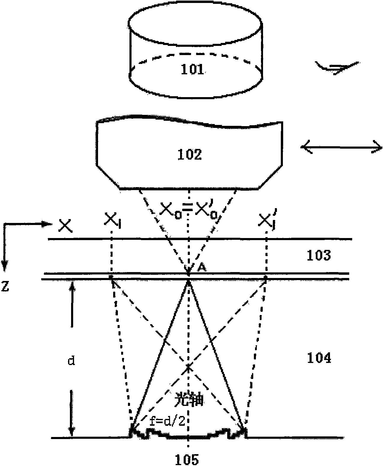
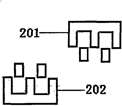
[0016] like figure 1 As shown, the exposure system 101 is located above the reticle 103 and the sample 104, and can be rotated by 180°. When exposure is required, the exposure system 101 is located directly above the reticle 103 and the sample 104. The template 103 and the sample 104 deviate by 90°; the microscope or CCD imaging device and its imaging optical system 102 are located between the exposure system 101, the reticle 103 and the sample 104, can move along the X-axis direction, and are positioned at the reticle 103 and the sample 104 during alignment Directly above, move out of the exposure field of view from the X direction during exposure. In this way, the microscope or CCD imaging device and its imaging optical system 102 can simultaneously capture the image 201 of the reticle alignment mark itself and the contour image 202 formed by the reflective zone plate, as shown in FIG. 2 , to achieve front-side overlay alignment.

[0017] The specific overlay alignment proc...


PUM


Abstract

This is a self-imaging overlay aligning method for the double-sided lithography machine involving the field of microelectronics special equipment technology. This method is used to achieve the overlay alignment of the sample and mask of double-sided lithography machine. This method uses the imaging technology of reflective zone plate, which uses the single-view-field microscope or CCD imaging system over the mask mark for alignment to achieve the overall technical program of double-sided aligning photolithography of the single optical head positive overlay alignment, positive twice (both positive and negative) exposure. This method provides a method to realize double-sided overlay alignment with one set of optical system only on the mask and sample side (i.e., positive side) in the double-sided lithography machine and effectively solves the technical problems as the complex structure, complicated operation and low overlay alignment accuracy of the other common aligning methods.

Description

Technical field: [0001] The invention relates to the technical field of special equipment for microelectronics, in particular to a method for realizing overlay alignment between a sample and a mask in a double-sided photolithography machine. Background technique: [0002] There are many alignment methods that can be selected in double-sided lithography machines, such as infrared alignment, four-objective alignment, double-mask alignment, and grating phase alignment. However, there are certain and even fatal flaws in these alignment methods. Among them, the shortcomings of infrared alignment are: poor observation conditions of infrared microscope, low alignment accuracy, slow alignment speed, and low productivity; when the wafer reaches a certain thickness, the infrared penetration ability is reduced, and alignment is very difficult; and cannot For exposure of wafers opaque to infrared light. The shortcomings of the four-objective lens alignment principle are: complex optic...

Claims


Application Information

Patent Timeline
Patent Type & Authority Applications(China)
IPC IPC(8): G03F7/20G03F9/00
Inventor 马平胡松唐小萍邢薇严伟
Owner INST OF OPTICS & ELECTRONICS - CHINESE ACAD OF SCI
Why Eureka
Try Eureka