Coaxial image system applied to LED laser cutting device

A technology of laser cutting and image system, applied in the field of coaxial image system and optical image system, to achieve the effect of unique design, excellent function and broad application prospect

Active Publication Date: 2009-10-21
SUZHOU DELPHI LASER +1
View PDF0 Cites 19 Cited by
  • Summary
  • Abstract
  • Description
  • Claims
  • Application Information

AI Technical Summary

Problems solved by technology

Generally, blue LED wafers are cut in two ways: tangent and back-cut. The tangent is the laser cutting from the surface of the GaN luminescent material, and the back-cut is cutting from the surface of the sapphire substrate material. The dicing line is generally marked on the upper surface of the wafer,

Method used


Image

  • Coaxial image system applied to LED laser cutting device
  • Coaxial image system applied to LED laser cutting device
  • Coaxial image system applied to LED laser cutting device

Examples


Embodiment Construction

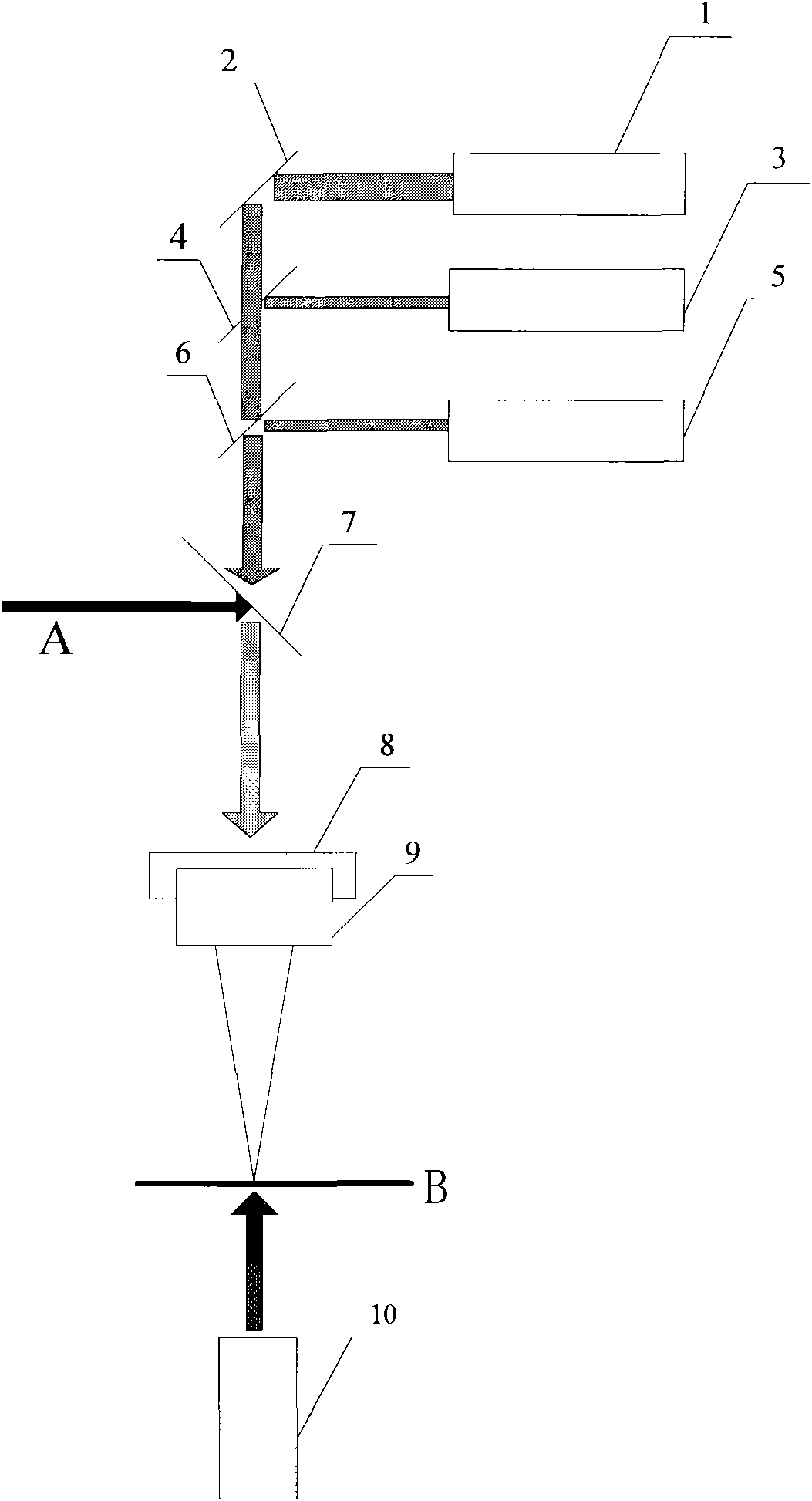
[0025] like figure 1 As shown, the coaxial image system applied to LED laser cutting equipment includes coaxial LED point light source module 1, 45-degree full reflection mirror 2, wide-angle CCD module 3, first 45-degree beam splitter 4, small field of view and high magnification Upper CCD module 5, second 45-degree beam splitter 6, wavelength selective mirror 7, LED ring light source 8, focusing mirror 9, small field of view and high magnification lower CCD module 10, coaxial LED point light source module 1, wide-angle CCD module Group 3 and the upper CCD module 5 with small field of view and high magnification are arranged side by side from top to bottom, the wavelength selective mirror 7 is installed between the upper CCD module 5 and the focusing mirror 9, and the LED ring light source 8 is closely attached to the focusing mirror 9 On the top, the focusing lens 9 is facing the workpiece B, and the CCD module 10 with a small field of view and high magnification is installe...


PUM


Abstract

The invention relates to a coaxial image system applied to an LED laser cutting device, comprising a coaxial LED point light source module, a 45-degree total reflection mirror, a wide-angle CCD module, a first 45-degree spectroscope, a small-vision field high-magnification upper CCD module, a second 45-degree spectroscope, a wavelength selection mirror, an LED ring light source, a focusing lens and a small-vision field high-magnification lower CCD module; the coaxial LED point light source module, the wide-angle CCD module and the small-vision field high-magnification upper CCD module are arrayed in parallel from top to bottom, the wavelength selection mirror is mounted between the CCD module and the focusing lens, the LED ring light source clings to the focusing lens which faces directly towards a workpiece, the small-vision field high-magnification lower CCD module is mounted below the workpiece. The invention realizes coaxial real-time image positioning function in the LED laser cutting device, combined usage of the wide-angle CCD and the small-vision field high-magnification upper CCD realizes micrometer-grade measurement accuracy, and the convenient switch of the small-vision field high-magnification upper CCD and the small-vision field high-magnification lower CCD meets the demands of front-cutting, back-cutting, surface coarsening and the cutting of back-aluminized wafer.

Description

technical field [0001] The invention relates to an optical image system, in particular to a coaxial image system applied to LED laser cutting equipment, and belongs to the technical field of laser precision processing. Background technique [0002] LED laser cutting equipment is a special laser equipment used for cutting GaN blue light LED wafers on sapphire substrates. Blue light LED wafers are usually grown on sapphire substrates by vapor phase deposition process GaN crystals, and finally on the wafers Several LED light-emitting units with independent light-emitting functions are formed by screen printing technology and electrodes. [0003] At present, blue LED wafer cutting equipment has been gradually upgraded from diamond knife cutting to laser cutting. With non-contact laser processing, the equipment must have precise positioning function. The reserved dicing width of general LED wafers is about 20-30um, even as narrow as 15um, while the laser processing affects the l...

Claims


Application Information

Patent Timeline
IPC IPC(8): B28D7/00B28D5/04B23K26/38G01B11/00H01L33/00
Inventor 赵裕兴徐海宾
Owner SUZHOU DELPHI LASER
Why Eureka
Try Eureka