

Preparation die for polymer optical fiber prefabricated bar and preparation method for the prefabricated bar
A technology of optical fiber preform and polymer, which is applied in the direction of cladding optical fiber, household appliances, optical components, etc. It can solve the problems of easy introduction of air bubbles between the core layer and the cladding layer, rough cladding core boundary, and difficulty in achieving single-mode fiber, etc. problems, to achieve the effect of good chemical stability and heat resistance of the material, smooth surface and time saving
- Summary
- Abstract
- Description
- Claims
- Application Information
AI Technical Summary
Problems solved by technology
Method used
Image

Examples
Embodiment 1
[0047] Example 1 Preparation of step-type azo-doped single-mode polymer optical fiber preform
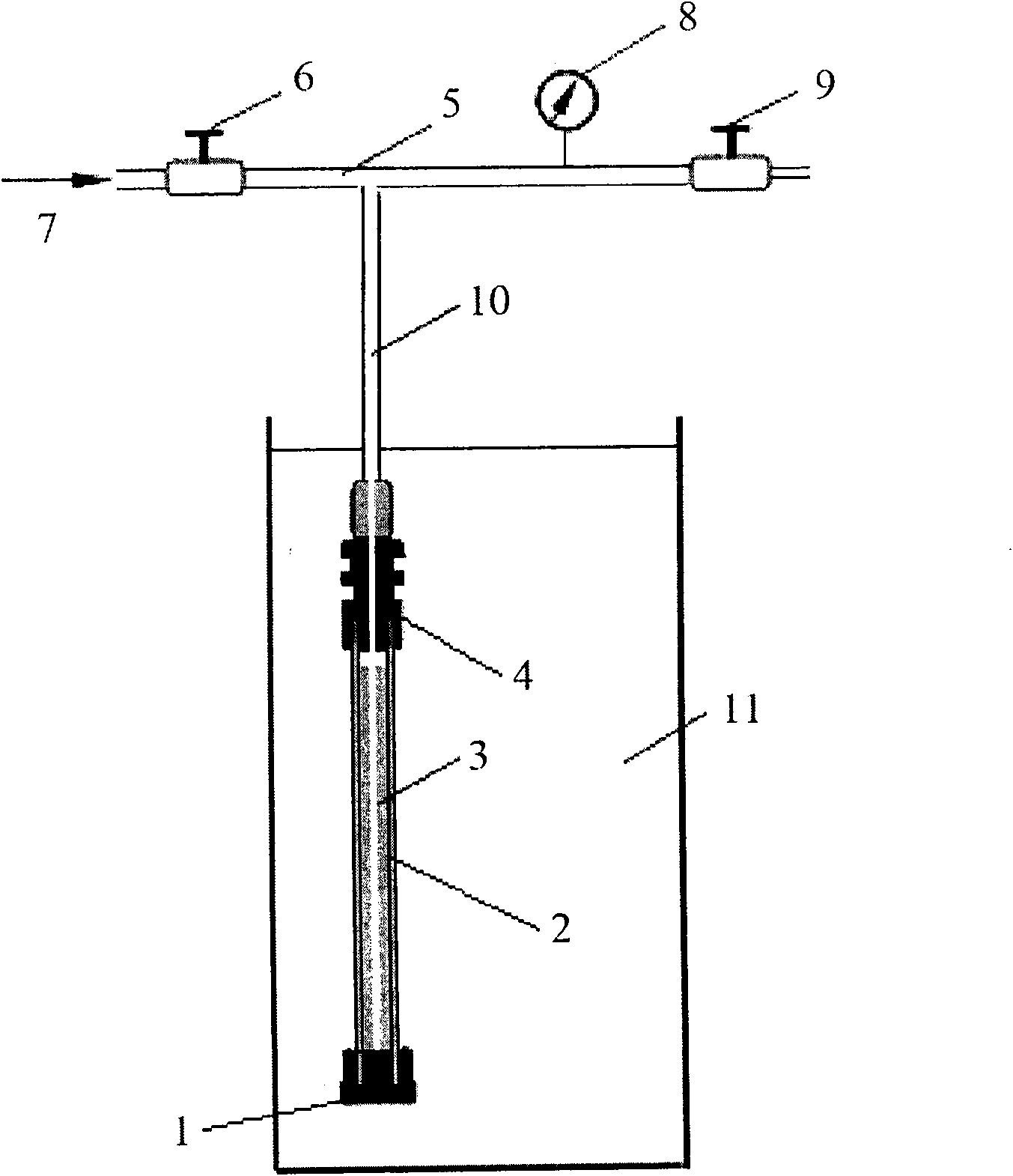
[0048] (1) Preparation and installation of reaction molds for polymer optical fiber preforms
[0049] Such as figure 1 As shown, a pressure-resistant fluoroplastic tube 2 with a length of about 30 cm is used as a polymerization container, and its lower end is closed with a nut-screw structure 1, and one end of a Teflon rope (polytetrafluoroethylene rope) 3 is fixed in the center. The Teflon rope is about 25cm long and has an original diameter of 0.84mm. After one end is fixed at the lower end of the polymerization container, it is stretched moderately so that the Teflon rope reaches a sufficient length to pass through the total length of the pressure-resistant fluoroplastic tube 2 and its top cover 4 . Fix the other end of the Teflon rope to the center of the pre-cover by using a nut-screw structure, so that the Teflon rope is straightened and fixed on the axis of the pressure-resi...
Embodiment 2
[0064] Example 2 Using the preform obtained by the preparation method provided by the present invention to make an optical fiber
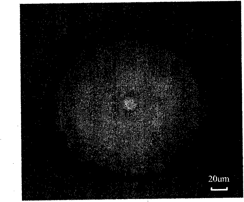
[0065] The step-type azo-doped single-mode polymer optical fiber preform obtained in Example 1 was used to draw it into an optical fiber with a fiber drawing machine. The drawing temperature is 120°C, and the core diameter of the optical fiber is controlled by adjusting the ratio of feeding speed and pulling speed. The characteristic fiber diameter is 183 μm, the core is 17 μm, and the refractive index difference between the cladding layer and the core layer is 0.0054. It can be seen that the fiber is single-mode at 1550 nm. (Such as figure 2 shown)
Embodiment 3
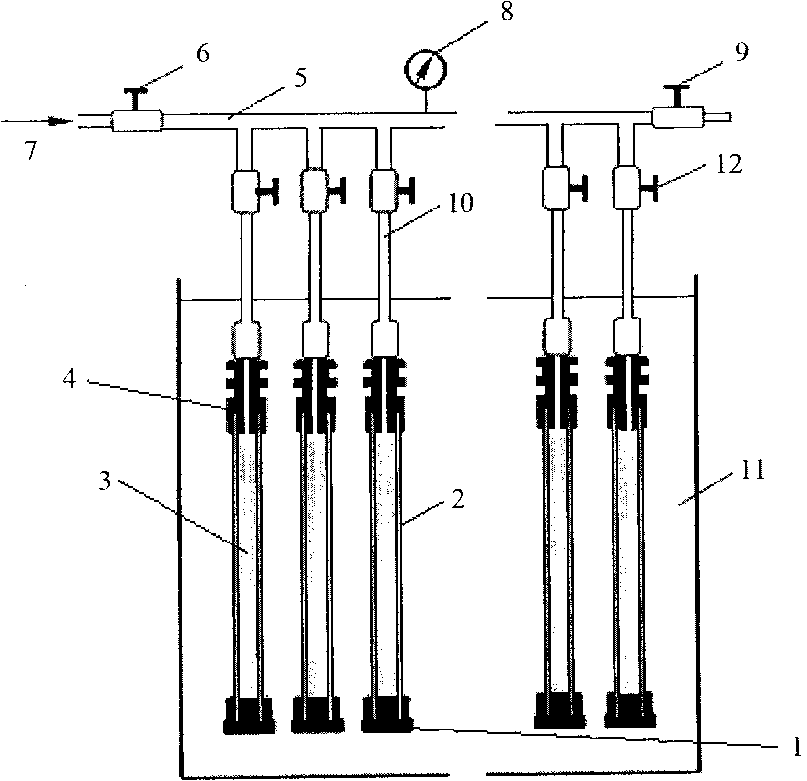
[0066] Embodiment 3 utilizes the reaction mold provided by the present invention to carry out batch production
[0067] The preparation of the reaction mold for the polymer optical fiber preform is the same as in Example 1.
[0068] Such as image 3As shown, several branch pipes 10 come out from the main pipe 5; branch valves 12 are installed on each branch pipe 10, and the lower end of the branch valve 12 is connected with the hole on the reaction mold top cover 4 of the polymer optical fiber preform. Several branch pipes are separated from the main pipe 5 to facilitate batch preparation, and polymer optical fiber preforms with different doping conditions or different proportions can be prepared by controlling the opening of each branch valve.
[0069] Other experimental conditions and processes are the same as in Example 1.
PUM
 Abstract
Description
Claims
Application Information