K-waveband dielectric disk-loaded circular waveguide feed filter

A technology of electric filter and dielectric film, which is applied in the field of isolated wave-transparent feeder, can solve problems affecting system performance and cannot meet the mechanical isolation requirements of radar antennas, and achieve low insertion loss and simple and convenient processing

Inactive Publication Date: 2009-11-04
BEIHANG UNIV
View PDF0 Cites 12 Cited by
  • Summary
  • Abstract
  • Description
  • Claims
  • Application Information

AI Technical Summary

Problems solved by technology

However, since the dielectric film hole filter needs to open a certain size hole on the loaded dielectric film to achieve resonance characteristics, it cannot meet the mechanical isolation requirements of the microwave circuit in the radar system and the ra

Method used


Image

  • K-waveband dielectric disk-loaded circular waveguide feed filter
  • K-waveband dielectric disk-loaded circular waveguide feed filter
  • K-waveband dielectric disk-loaded circular waveguide feed filter

Examples


Embodiment 1

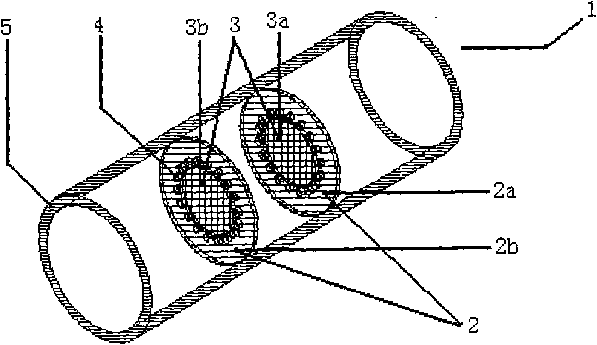
[0034] according to image 3Shown is a preferred embodiment of a K-band dielectric diaphragm-loaded circular waveguide feed filter 1 based on the present invention. In this preferred embodiment, the working center frequency is 24GHz and the bandwidth is 1.5GHz. The inner radius of the cylindrical metal cavity 5 is 4.3mm, the radius of the dielectric diaphragms 3a and 3b is 2.35mm, the distance between the two dielectric diaphragms 3a and 3b is 7mm, and the diameter of the metallized via hole 4 is 0.5mm. The distance between the edge of the metallized via hole 4 and the edge of the dielectric diaphragm 3 is 0.25 mm. In the invention, the diameter of the metallized via hole 4 can be as small as 0.2 mm. The metallized via holes 4 have an angular interval of 15 degrees and are uniformly arranged along the edge of the dielectric diaphragm 3 . The medium used to manufacture the microwave substrate 2 of the dielectric diaphragm 3 is alumina with a purity of 99% and a dielectric co...

Embodiment 2

[0036] according to image 3 Shown is another preferred embodiment of a K-band dielectric diaphragm-loaded circular waveguide feed filter 1 based on the present invention. In this preferred embodiment, the working center frequency is 20GHz and the bandwidth is 1.1GHz. The inner radius of the circular waveguide 5 is 4.7mm, the radius of the dielectric diaphragms 3a and 3b is 2.8mm, the distance between the two dielectric diaphragms 3a and 3b is 7.8mm, and the diameter of the metallized via hole 4 is 0.5mm. The distance between the edge of the metallized via hole 4 and the edge of the dielectric diaphragm 3 is 0.25 mm. In the invention, the diameter of the metallized via hole 4 can be as small as 0.2mm. The metallized via holes 4 have an angular interval of 15 degrees and are uniformly arranged along the edge of the dielectric diaphragm 3 . The medium used to manufacture the microwave substrate 2 of the dielectric diaphragm 3 is alumina with a purity of 99% and a dielectric c...

Embodiment 3

[0038] according to image 3 Shown is another preferred embodiment of a K-band dielectric diaphragm-loaded circular waveguide feed filter 1 based on the present invention. In this preferred embodiment, the working center frequency is 22GHz and the bandwidth is 1.3GHz. The inner radius of the circular waveguide 5 is 4.7mm, the radius of the dielectric diaphragms 3a and 3b is 2.8mm, the distance between the two dielectric diaphragms 3a and 3b is 8.3mm, and the diameter of the metallized via hole 4 is 0.6mm. The distance between the edge of the metallized via hole 4 and the edge of the dielectric diaphragm 3 is 0.25mm. In the invention, the diameter of the metallized via hole 4 can be as small as 0.2mm. The metallized via holes 4 have an angular interval of 15 degrees and are uniformly arranged along the edge of the dielectric diaphragm 3 . The medium used to manufacture the microwave substrate 2 of the dielectric diaphragm 3 is beryllium oxide with a purity of 99.5% and a die...


PUM

PropertyMeasurementUnit
Inner radiusaaaaaaaaaa

Abstract

The invention relates to a K-waveband dielectric disk-loaded circular waveguide feed filter (1) for a physical position measurement radar system, comprising a circular waveguide (4) which connects an antenna and a microwave circuit and two dielectric disks (3) which are loaded in the circular waveguide (4), the electromagnetic wave transmission mode in the circular waveguide (4) is TE11 mode, thetwo dielectric disks (3) loaded in the circular waveguide are processed by a commercial microwave substrate (2), the microwave substrate (2) etches the circular dielectric disks (3) through the pattern plating etching method, and a series of metal through holes (5) which surround the dielectric disks are processed on the outer rings of the dielectric disks, thereby forming an equivalent circular waveguide wall. The K-waveband dielectric disk-loaded circular waveguide feed filter can directly use the microwave substrate with high dielectric constant and good thermal resistance, the processing of the parts is very simple and the cost is low. As the dielectric disks in the filter have thin thickness, less loss and good matching performance, the insertion loss of the feed filter in the workingband is less than 0.1dB. In addition, as the dielectric disks are solid structures and have good dust-proof and thermal insulating performances, the feed filter can effectively protect a microwave circuit part of the radar system.

Description

technical field [0001] The invention relates to a dielectric diaphragm-loaded circular waveguide feed filter working in the K-band, which can pass microwave signals of a certain frequency and suppress microwave signals outside the designed frequency range, and is mainly used in level measurement radar systems. Isolated wave-transparent feeder. Background technique [0002] Microwave passive filter is an important device in microwave and millimeter-wave radar systems, and its performance often directly affects the quality of the entire system. In recent years, with the rapid development of microwave and millimeter wave technology, the demand for such devices in the fields of microwave, millimeter wave communication, microwave navigation, guidance, telemetry and remote control, satellite communication and military electronic countermeasures has been increasing. At present, there are waveguide filters, coaxial line filters, stripline filters, microstrip line filters, etc. acco...

Claims


Application Information

Patent Timeline
IPC IPC(8): H01P1/20H01P1/212
Inventor 万亮李志平许鼎何国瑜苗俊刚
Owner BEIHANG UNIV
Why Eureka
Try Eureka