
Reconfigurable double-antenna system for mobile terminal

A mobile terminal, dual-antenna technology, applied in directions such as antennas, antenna supports/installation devices, and devices that enable antennas to work in different frequency bands at the same time, can solve the problems of limited effect, reduced antenna efficiency, and large mutual coupling of antenna units, etc. Achieve the effect of simple manufacturing process, compact structure and easy integration

Inactive Publication Date: 2009-11-11
TSINGHUA UNIV
View PDF0 Cites 34 Cited by
  • Summary
  • Abstract
  • Description
  • Claims
  • Application Information

AI Technical Summary

Problems solved by technology

[0005] For small-sized mobile terminals, due to the limited space occupied by the antenna units, the effects of space and polarization diversity are limited, and the mutual coupling between the antenna units is large, making it difficult to reconstruct the antenna pattern and reduce the efficiency of the antenna. Reduce the capacity of the communication system

Method used


Image

  • Reconfigurable double-antenna system for mobile terminal
  • Reconfigurable double-antenna system for mobile terminal
  • Reconfigurable double-antenna system for mobile terminal

Examples


Embodiment Construction

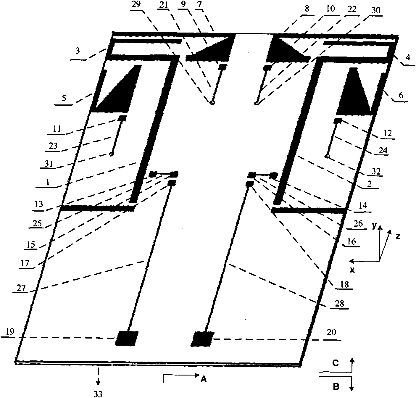
[0031] The present invention proposes a reconfigurable dual-antenna system for wireless mobile communication terminals. The three-dimensional structural diagram is as follows figure 1 shown. The antenna structure is printed on the FR-4 dielectric board with a dielectric constant of 4.4, including the radiation element of the antenna, the feeder line, the DC bias circuit and the metal ground. Wherein, the radiating unit includes inverted monopole branch radiating units 3, 4 and parasitic radiating units 5, 6, 7, 8, and the monopole radiating unit and the parasitic radiating unit are connected by a PIN diode, such as image 3 shown. Inside the two feeders and below the parasitic radiation units 5, 6, 7, and 8 are DC bias circuits of four PIN diodes, wherein the metal sheets 9, 10, 11, 12, 13, and 14 are solder joints of the inductors, and the other One end is respectively welded to the parasitic radiation unit and the feeder, and a 22nH inductance is used to prevent the AC cur...


PUM


Abstract

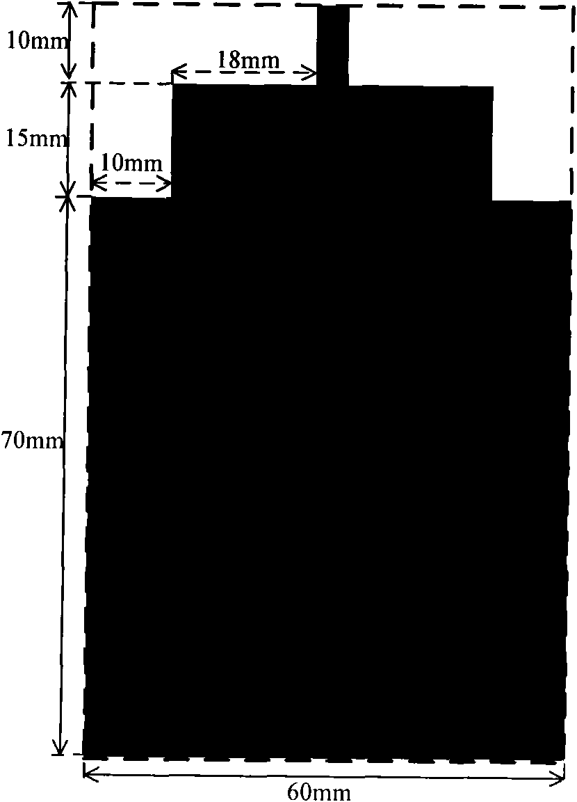
A reconfigurable double-antenna system used for a mobile terminal belongs to the field of mobile terminal multi-antenna and is characterized in that the reconfigurable antenna system is printed on a printed circuit board and comprises a radiation unit, a feeder wire, a direct current power supply circuit and a metal floor. The radiation unit comprises a spurious radiation structure and a monopolestructure which are connected by a PIN diode switch. The antenna specification is 25 X 10 X 0.8 mm<3> + 18 X 10 X 0.8 mm<3>, and antenna feed is conducted by a 50-Ohm microstrip line. A direct current biasing circuit below the radiation unit controls the connection and disconnection of a PIN diode. An isolated alternate current inductor is used in a direct current path to prevent the alternating current on the radiation unit from passing through. The metal floor is one of the two surfaces of the circuit board, which does not consist of the antenna radiation unit, and is used for simulating rectangular metal patches on parts other than antennas in the mobile terminal of a wireless communication system. The reconfigurable double-antenna system has the advantages of compact structure and easy integration and a function of supporting the reconfiguration of a directional diagram and is applicable to a mobile communication terminal, in particular to a reconfigurable double-antenna structure of a small mobile terminal.

Description

technical field [0001] The invention belongs to the field of mobile terminal antenna design, in particular to a reconfigurable dual-antenna system structure design for a mobile terminal in a complex communication environment. Background technique [0002] Antenna systems usually work in a complex mobile propagation environment, and radio waves will be attenuated in many ways when propagating in the air. In addition, there are multiple propagation paths at the transmitting and receiving ends of the wireless communication link, and the effectiveness of multipath propagation on communication have a serious impact on reliability. It is difficult to maintain good performance in a complex propagation environment with only a single antenna. It is necessary to use reconfigurable antenna technology and multiple-input multiple-output (MIMO) technology to increase spectrum utilization, improve signal-to-noise ratio, improve communication quality, and reduce transmit power. [0003] R...

Claims


Application Information

Patent Timeline
IPC IPC(8): H01Q1/38H01Q1/24H01Q5/00H01Q13/08H01Q23/00H01Q5/371
CPCY02D30/70
Inventor 蔡亚星杜正伟龚克
Owner TSINGHUA UNIV
Learn More