Standby power supply device

A backup power supply and electrode technology, applied in circuit devices, emergency power supply arrangements, circuits, etc., can solve problems such as being unable to reach at the same time, battery leakage, and no power.

Inactive Publication Date: 2010-01-13
LITE ON TECH CORP
View PDF0 Cites 10 Cited by
  • Summary
  • Abstract
  • Description
  • Claims
  • Application Information

AI Technical Summary

Problems solved by technology

Although capacitors are relatively simple in manufacturing process, they can only be used as short-term energy storage due to their small storage capacity
The traditional battery mainly uses chemical energy to store energy, so its energy storage density is significantly better than that of general capacitors, and it can be applied to various power supply devices. However, its disadvantage is: the instantaneous power it can generate The output will be limited by the chemical reaction rate, so it cannot be charged and discharged quickly or high-power output, and the number of charge and discharge is limited, and various problems are likely to arise when overcharged; for example: the batteries currently used, although advertised as repeatable use, but still has its life limit
In the case of repeated charging and discharging or long-term non-use, the capacity of the battery will decrease and it will be easily damaged. The reason is that the battery uses chemical energy to convert into electrical energy. When the activity of all the compounds is used up or nearly used up, new chemical reactions can no longer be carried out, which leads to the aging of the battery and the end of its service life
[0007] A supercapacitor is a component between a battery and a capacitor, also known as an electrical double-layer capacitor (Electrical Double-Layer Capacitor). Because it uses part of the physical energy storage and part of t...

Method used


Image

  • Standby power supply device
  • Standby power supply device
  • Standby power supply device

Examples


Embodiment Construction

[0046] In order to further explain the technical means and effects of the present invention to achieve the intended purpose of the invention, the specific implementation, structure, characteristics and effects of the backup power supply device proposed according to the present invention will be described below in conjunction with the accompanying drawings and preferred embodiments. Details are as follows.

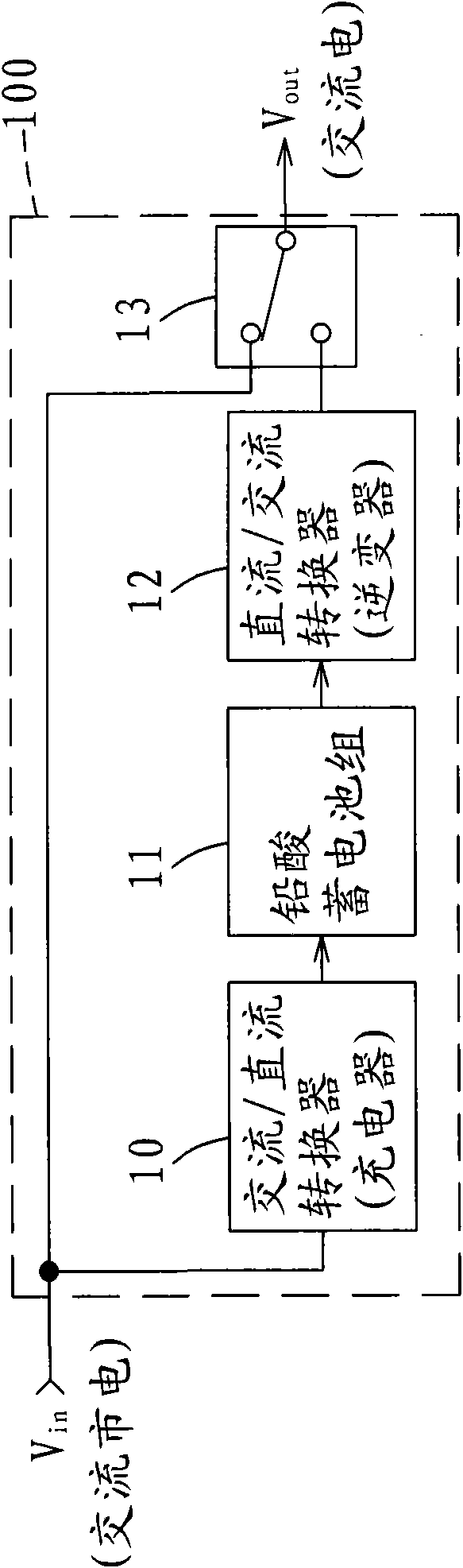
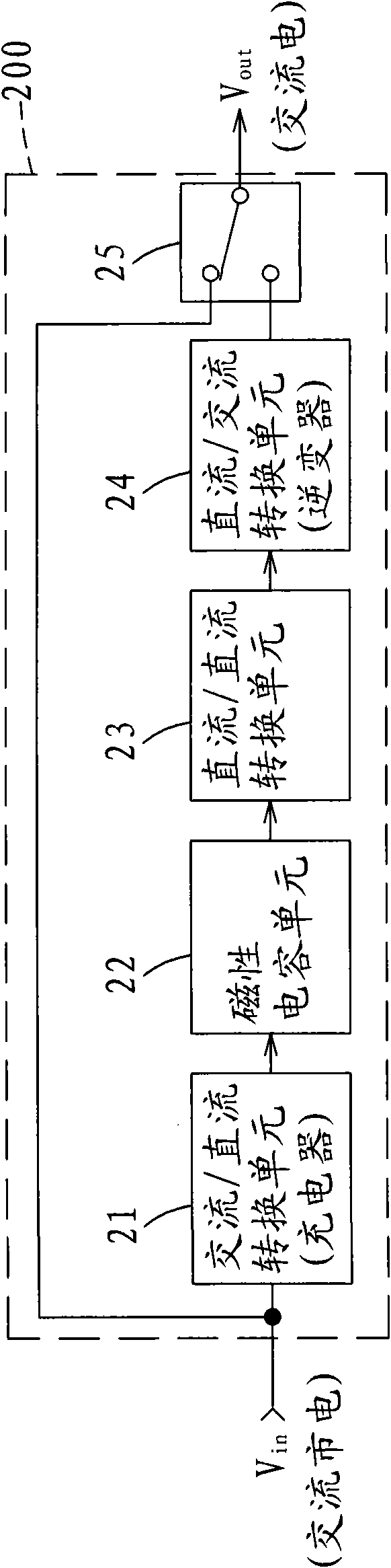
[0047] The foregoing and other technical contents, features and effects of the present invention will be clearly presented in the following detailed description of two preferred embodiments with reference to the drawings. The main difference between these two embodiments is that one of the embodiments is an uninterruptible power supply (UPS) that requires a switch (control unit) as an example, and the other embodiment is based on a UPS that does not need a switch (control unit). Take the emergency power supply unit (EPS) as an example.

[0048] see figure 2 Shown is a sc...


PUM


Abstract

The invention relates to a standby power supply device, which is connected between an AC commercial power and a load so as to supply power to the load, and comprises an AC/DC converting unit used for converting the AC commercial power into DC for output, a magnetic capacitor unit charged by the DC so as to store energy, a DC/DC converting unit used for carrying out the boost/buck conversion for the discharge voltage of the magnetic capacitor so as to output a fixed voltage, an AC/DC converting unit used for converting the fixed voltage into AC for output, and a control unit used for selectively connecting the AC commercial power or the AC/DC converting unit so as to output the AC commercial power or the AC to the load. The standby power supply device uses the magnetic capacitor as an energy storing unit so as to have the advantages of low cost, high energy storing density, small volume, light weight, large capacity, no maintenance, long service life, environment-friendly property, low pollution and the like.

Description

technical field [0001] The invention relates to a backup power supply device, in particular to a backup power supply device using a magnetic capacitor as an electric storage element. Background technique [0002] With the development of electric power application technology, electronic devices that rely on electric power to operate are constantly being developed, making people's demand for electric power increasing day by day, so that sudden power outages often bring impact and inconvenience to people's lives, especially for factories. Once the power supply of particularly important load equipment in production lines or life is interrupted, it will often cause major economic losses to the industry or users. However, no matter how advanced the current power grid facilities are, unexpected power outages are still inevitable. Therefore, when the mains power is cut off, the uninterruptible power system (UPS) that can provide the power required by the load in time and is widely u...

Claims


Application Information

Patent Timeline
IPC IPC(8): H02J9/00H02J15/00H01G4/00H01G4/005H01G4/008H01G4/06
CPCY02B70/30Y04S20/20
Inventor 许跃腾郑宇竣
Owner LITE ON TECH CORP
Why Eureka
Try Eureka