Schottky concretionary battery with protection ring structure and manufacture method thereof

A technology of nodule battery and protection ring, which is applied in the fields of semiconductor, nuclear physics and micro-energy, can solve the problems of low sensitivity and energy conversion efficiency, and achieve the effect of improving energy conversion efficiency, increasing open circuit voltage and increasing sensitivity

Inactive Publication Date: 2010-01-20
NANTONG HENGDING HEAVY DUTY MACHINE TOOL +1
View PDF0 Cites 10 Cited by
  • Summary
  • Abstract
  • Description
  • Claims
  • Application Information

AI Technical Summary

Problems solved by technology

[0006] The purpose of the present invention is to overcome the shortcomings of low sensitivity and energy conversion efficiency caused by the current leakage of existing micro-nuclear batteries, to provide a new micro-nuclear battery structure with smaller leakage current and higher conversion efficiency, and to provide a Easy-to-manufacture preparation method

Method used


Image

  • Schottky concretionary battery with protection ring structure and manufacture method thereof
  • Schottky concretionary battery with protection ring structure and manufacture method thereof
  • Schottky concretionary battery with protection ring structure and manufacture method thereof

Examples


specific Embodiment 1

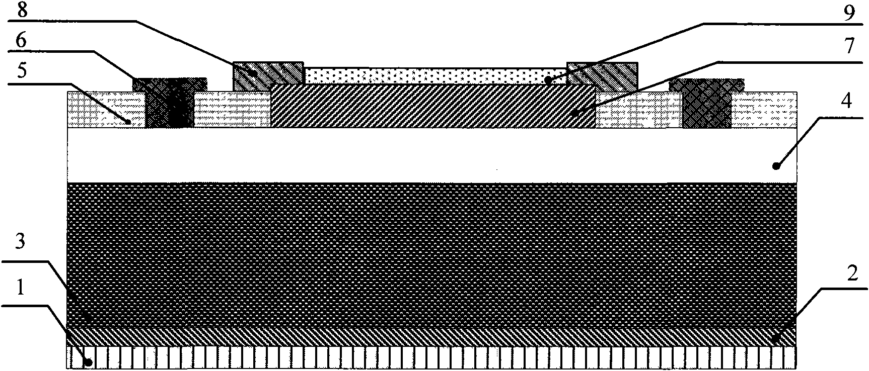
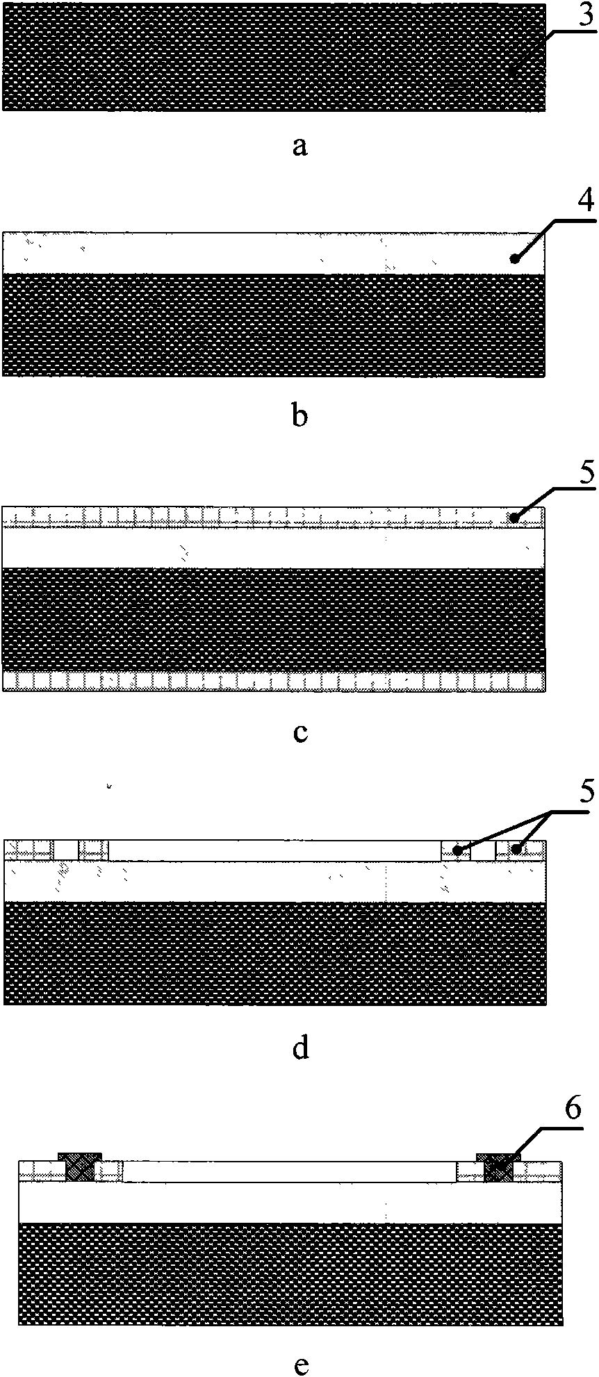
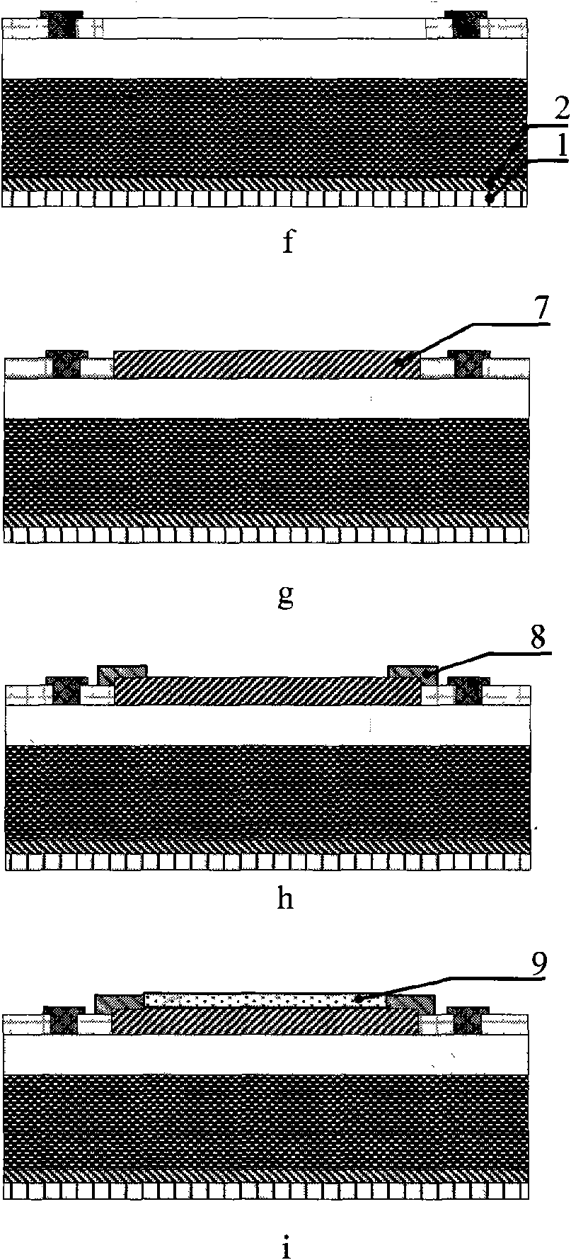
[0032] refer to figure 1 , image 3 , the Schottky nodule cell with guard ring structure in this embodiment includes isotope 9, upper electrode metal layer 8, barrier metal layer 7, guard ring 6, passivation layer 5, intrinsic i layer 4, n + Type SiC layer 3, ohmic contact layer 2, bottom electrode metal layer 1; where n + The doping concentration of type SiC layer 3 is 5×10 17 cm -3 , a thickness of 300 μm, a circular shape; a thickness of 10 μm, a doping concentration of 5×10 14 cm -3 , the intrinsic i layer 4 with the same shape as the n+ type SiC layer 3 is located at n + type SiC layer 3; the shape of the barrier metal layer 7 can be any shape such as circular or square; the guard ring 6 is located in the outer annular area of ​​the barrier metal layer 7 above the intrinsic i layer 4, and the inner ring of the guard ring 6 and The outer ring spacing of the barrier metal layer 7 is 100 μm; the shape of the upper electrode metal layer 8 is circular, spanning the inte...

specific Embodiment 2

[0044] refer to figure 1 , Figure 4 , the present embodiment is a Schottky nodule cell with a guard ring structure, including isotope 9, upper electrode metal layer 8, barrier metal layer 7, guard ring 6, passivation layer 5, intrinsic i layer 4, n + Type Si layer 3, ohmic contact layer 2, bottom electrode metal layer 1; n + The doping concentration of type Si layer 3 is 5×10 16 cm -3 , a square shape; the thickness is 20 μm, and the doping concentration is 5×10 14 cm -3 Intrinsic i layer 4 located at n + The front side of type Si layer 1; The shape of barrier metal layer 7 can be any shape such as circle or square; Guard ring 6 is positioned at the peripheral annular area of ​​barrier metal layer 7 above intrinsic i layer 4, guard ring 6 inner ring and The distance between the outer rings of the barrier metal layer 7 is 200 μm; the upper electrode metal layer 8 is two protrusions drawn from the interface between the passivation layer 5 and the barrier metal layer 7; t...


PUM


Abstract

The invention discloses a Schottky concretionary battery with a protection ring structure and a manufacture method thereof, and belongs to the field of semiconductor, nuclear physics and micro power. The protection ring 6 of the battery is positioned at the peripheral annular region of a potential barrier metal layer 7 above an intrinsic i layer 4. Electronic signals are led out of an interface of a passivation layer 5 and the potential barrier metal layer 7 through a top electrode metal layer 8. All regions except the potential barrier metal layer 7 and the protection ring 6 above the intrinsic i layer 4 are covered by the passivation layer 5. Isotope 9 is covered above the potential barrier metal layer 7. An n<+>-type semiconductor 3, an Ohmic contact layer 2 and a bottom electrode metal layer 1 with the same shape and size are arranged under the intrinsic i layer 4 in order. In addition, the invention further discloses the manufacture method for the atomic battery. The micro concretionary battery with the protection ring inhabits the influence of surface leakage and interface-state current on radiation generated current, indirectly improves an open circuit voltage, and also increases the sensibility of components for low energy radioactive source so as to improve the energy conversion efficiency of components.

Description

technical field [0001] The invention belongs to the fields of semiconductor, nuclear physics and micro-energy, and in particular relates to a Schottky junction micro-nuclear battery and a preparation method thereof. Background technique [0002] Micro-nuclear batteries can solve the long-term power supply problems of micro-pipe robots, implanted micro-systems, wireless sensor node networks, artificial cardiac pacemakers and portable mobile electronic products; Electric energy is superior to the traditional thermoelectric radioisotope battery (RTG, RadioisotopeThermoelectric Generator) that requires a thermal insulation layer, and is more suitable for miniaturization, light weight and integration, and is expected to replace solar cells and thermoelectric radioisotope batteries in the fields of aerospace and aviation Solve the long-term power supply problems of micro / nano satellites, deep space unmanned probes and ion thrusters. [0003] refer to Figure 5 , the document "CHI...

Claims


Application Information

Patent Timeline
Patent Type & Authority Applications(China)
IPC IPC(8): G21H1/06
Inventor 乔大勇苑伟政臧博姚贤旺吕湘连
Owner NANTONG HENGDING HEAVY DUTY MACHINE TOOL
Why Eureka
Try Eureka