High-frequency quick-recovery diode

A technology for recovering diodes and diodes, applied in electrical components, electrical solid devices, circuits, etc., can solve the problems of high chip price, difficult procurement, short reverse recovery time, etc., to achieve convenient procurement, reduce production costs, and improve withstand voltage. performance effect

Inactive Publication Date: 2010-01-20
CHANGZHOU GIANTION PHOTOELECTRICITY IND DEV
View PDF0 Cites 16 Cited by
  • Summary
  • Abstract
  • Description
  • Claims
  • Application Information

AI Technical Summary

Problems solved by technology

[0003]Traditional high-frequency fast recovery diodes are composed of multiple fast recovery diode chips, which have a short reverse recovery time and high endurance pressure performance, but such chips are not only expensive, difficult to purchase, and sometimes need to be imported

Method used


Image

  • High-frequency quick-recovery diode
  • High-frequency quick-recovery diode

Examples


Embodiment Construction

[0011] The present invention is described in further detail below in conjunction with the embodiment that accompanying drawing provides.

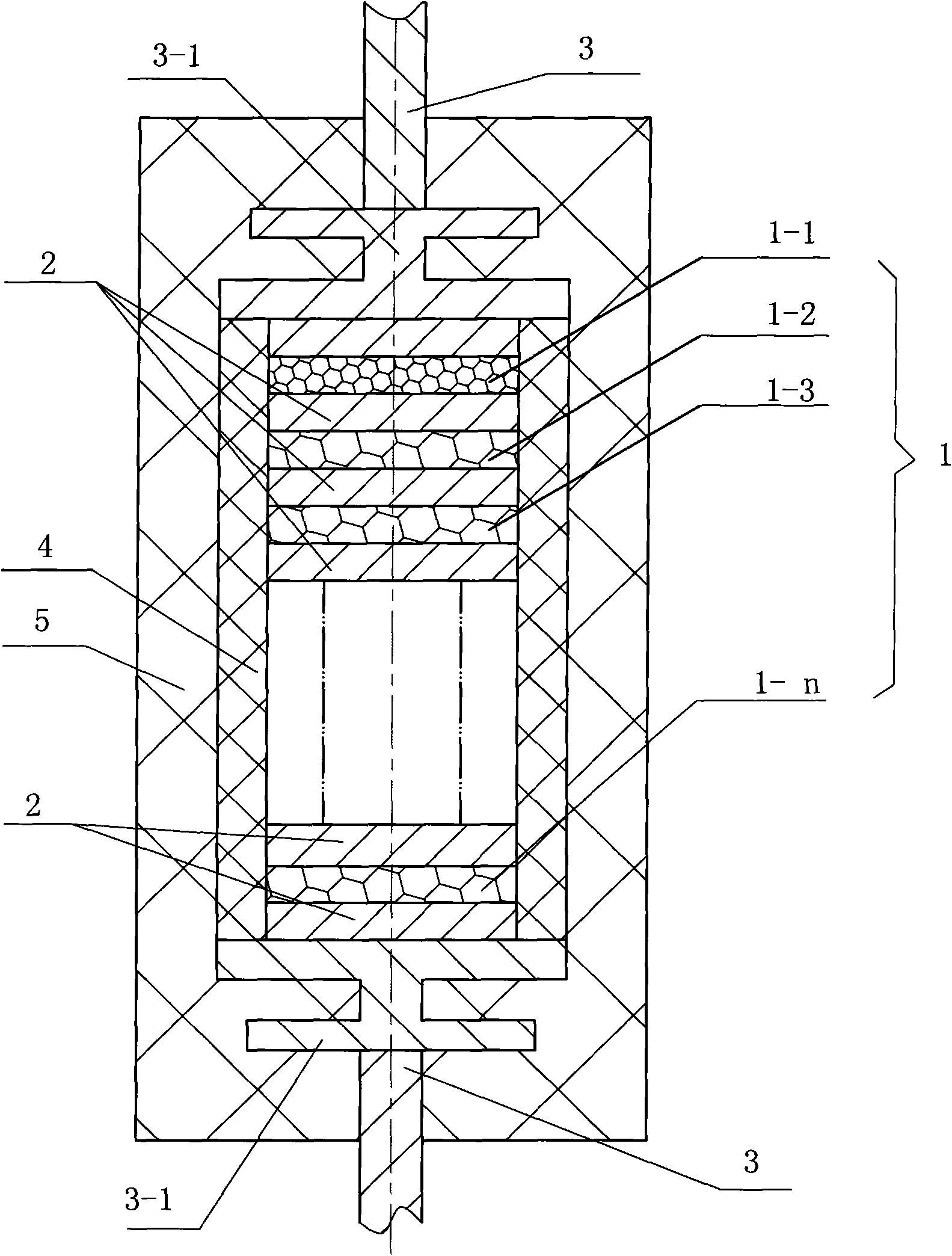
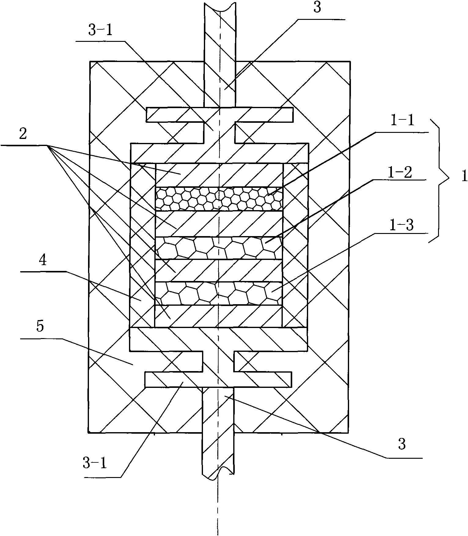
[0012] figure 1 It is a structural schematic diagram of Embodiment 1 of the present invention, such as figure 1 As shown, a high-frequency fast recovery diode includes a diode chip set 1, a soldering piece 2, a lead wire 3, a lead head 3-1, a rubber coating layer 4 and a plastic package 5; the diode chip set 1 includes n pieces of diode chips 1- 1, 1-2, 1-3, ... 1-n, arranged in the order of the same polarity, each piece of diode chip 1-1, 1-2, 1-3, ... Both sides of .1-n are provided with a soldering piece 2 and connected to the welding piece 2, and the end faces of the lead heads 3-1 of the two diode leads 3 are respectively connected to the welding pieces 2 at both ends of the diode chip set 1, and the diode chip set 1 and the outer periphery of the soldering piece 2 are provided with a rubber coating layer 4, and the two lead heads 3-...


PUM


Abstract

The invention relates to a high-frequency quick-recovery diode which comprises a diode chip set, a lug plate, leading wires, lead heads, a packet layer and a plastic-sealed body, wherein the diode chip set comprises n diode chips ranked in the sequence of polarity in the same direction, one to n-1 sheets of chips are quick-recovery diode chips, and the rest chips are common rectifier diode chips, and both sides of each diode chip are respectively provided with a lug plate which is mutually connected with the lug plate; the end surfaces of the lead heads of the two diode leading wires are respectively connected with the lug plates at both ends of the diode chip set; the periphery of the diode chip set and the lug plate is provided with a packet layer; the periphery of the two lead heads and the packet layer is provided with the plastic-sealed body; the plastic-sealed body is a cylinder or a square cylinder. Compared with a traditional high-frequency quick-recovery diode, the invention has the advantages of short reverse recovery time, high pressure-proof performance, low price and convenient purchase, and thereby reducing the production cost of the high-frequency quick-recovery diode. The invention is suitable for industrialized large-scale production.

Description

technical field [0001] The invention belongs to high-frequency diodes in the field of semiconductor devices, in particular to the structure of multi-crystal grain high-frequency fast recovery diodes. Background technique [0002] At present, electronic technology has been widely used in various fields of the national economy, has developed very rapidly, has the characteristics of convenient control, high efficiency and energy saving, and has been listed as one of the key technologies for key development by the country. The development trend of electronic technology is high voltage and large capacity, fast high frequency and module intelligence. High frequency fast recovery diode is a new type of semiconductor device that has come out in recent years. It has good switching characteristics, short reverse recovery time, large forward current, Small size, easy installation and other advantages, widely used in switching power supply, pulse width modulator, uninterruptible power s...

Claims


Application Information

Patent Timeline
Patent Type & Authority Applications(China)
IPC IPC(8): H01L25/07H01L23/52
CPCH01L25/074H01L23/3107H01L23/051H01L29/861H01L25/117H01L23/3135H01L23/66H01L24/42H01L2924/0002H01L2924/00
Inventor 吕全亚陈云峰杨吉明
Owner CHANGZHOU GIANTION PHOTOELECTRICITY IND DEV
Why Eureka
Try Eureka