Flue gas purifying system and method

A flue gas purification system and flue gas technology, applied in the field of flue gas purification, can solve the problems of inability to pulverize or burn completely, interval for a period of time, and insufficient burning of garbage, and achieve a simple structure, uniform discharge and stable operation. Effect

A flue gas purification system and flue gas technology, applied in the field of flue gas purification, can solve the problems of inability to pulverize or burn completely, interval for a period of time, and insufficient burning of garbage, and achieve a simple structure, uniform discharge and stable operation. Effect

CN101644437AActive Publication Date: 2010-02-10JIANGSU YIJIN ENVIRONMENTAL PROTECTION TECH CO LTD

Image

  • Flue gas purifying system and method
  • Flue gas purifying system and method
  • Flue gas purifying system and method

Examples


Embodiment Construction

[0043] The specific implementation manners of the present invention will be further described in detail below in conjunction with the accompanying drawings and embodiments. The following examples are used to illustrate the present invention, but are not intended to limit the scope of the present invention.

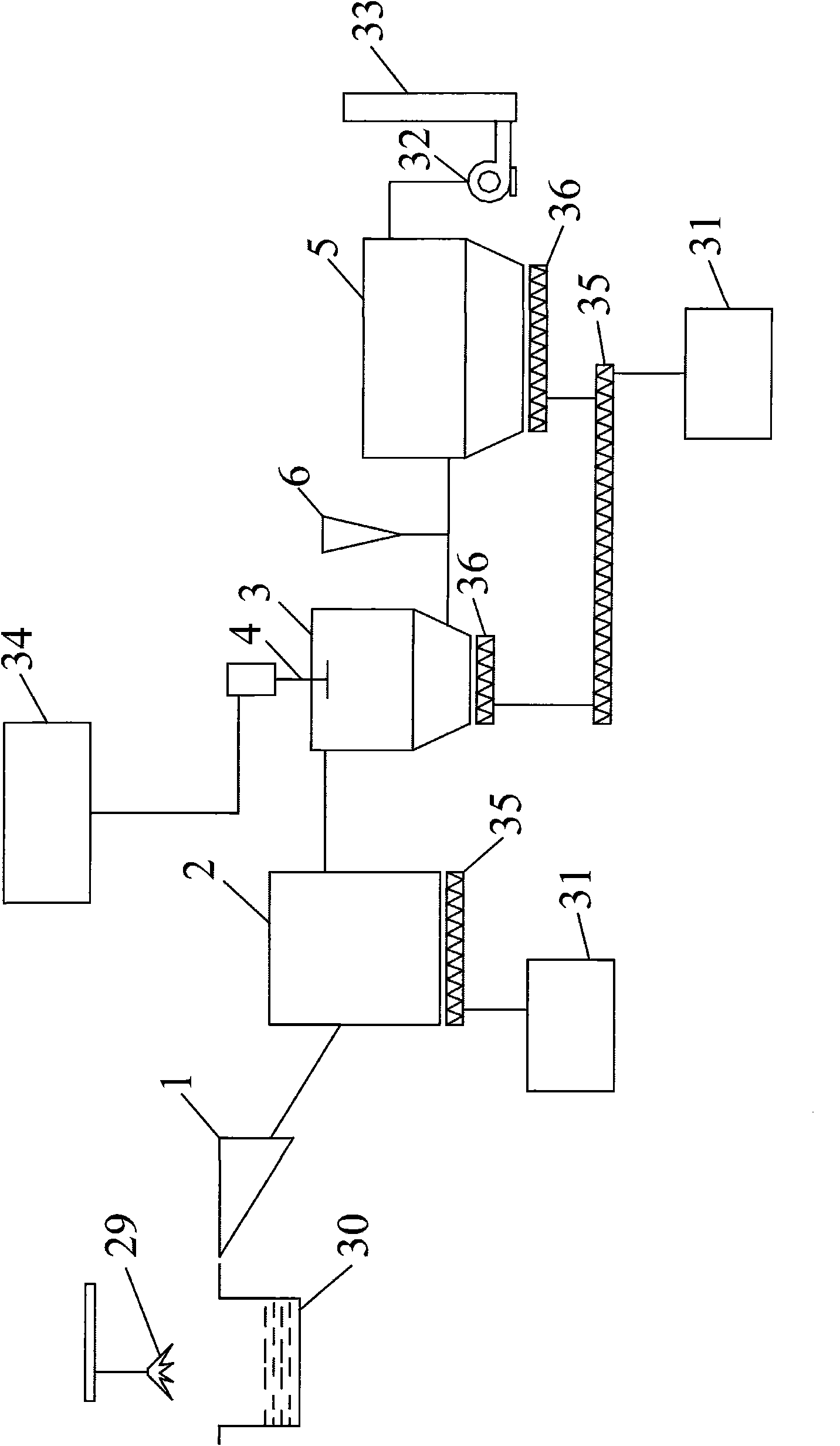
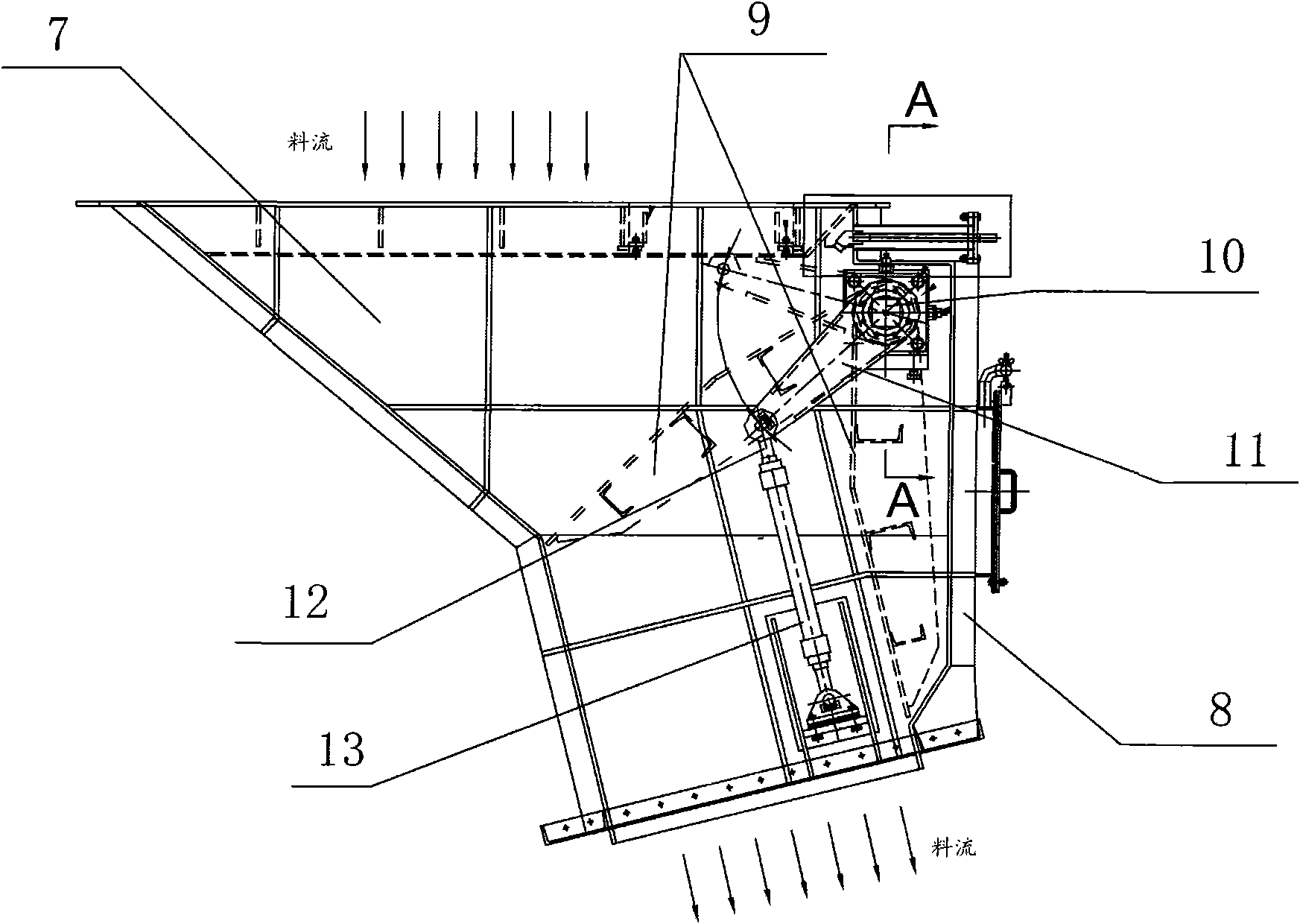
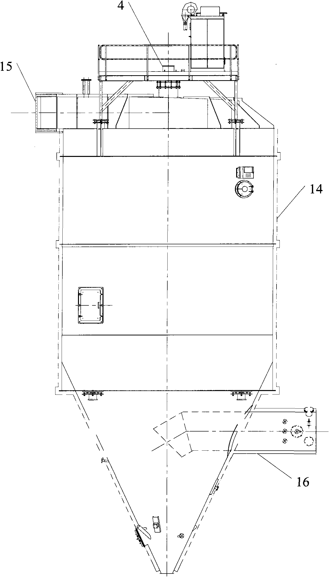
[0044]The object of the present invention is to provide a flue gas purification system, figure 1 is a schematic diagram of the system structure of an embodiment of the present invention; figure 2 It is a schematic structural view of the feeding hopper in the system of the embodiment of the present invention; image 3 is a schematic structural view of the reaction tower in the system of the embodiment of the present invention; Figure 4 It is a structural schematic diagram of the bypass valve in the system of the embodiment of the present invention; Figure 5 It is a structural schematic diagram of the gate valve in the system of the embodiment of the present invention;...


PUM


Abstract

The invention discloses a flue gas purifying system and a method. The system comprises a feed bin, a reaction tower and a deduster, wherein, the feed bin is used for transporting the garbage to a garbage incinerator when the garbage amount meets the primary combustion amount of the garbage incinerator; the reaction tower is connected with the garbage incinerator by a pipeline to be used for the flue gas to react with the lime slurry ejected from a rotary sprayer; the deduster is connected with the reaction tower by the pipeline to be used for dedusting of the flue gas treated by the reaction tower. The system of the invention is high in safety, simple in operation, high in purification efficiency and durable in use.

Description

technical field [0001] The invention relates to flue gas purification technology, in particular to a flue gas purification system and method. Background technique [0002] Conventional waste disposal methods include landfill, incineration and composting. Garbage incineration has attracted much attention due to its advantages of complete harmlessness, short processing time, heat recovery and small footprint. The flue gas purification system is the key to the pollution control of waste incineration. After the flue gas is purified, the emission concentration of various pollutants should meet the requirements of the national standard GWKB3-2000. Flue gas purification generally consists of three parts: deacidification, activated carbon adsorption, and dust removal. The processes commonly used at home and abroad are mainly semi-dry method / dry method + bag filter, among which deacidification technology is the core of waste incineration flue gas purification system. [0003] At p...

Claims


Application Information

Patent Timeline
10 Feb 2010
Publication
CN101644437A
IPC
F23G5/00; F23G5/44; F23J15/02; B01D53/78; F16K3/18; F16K31/60; F16K3/314
Inventors
宋正兴; 陈砚雄