Seal structure at sintering ring cold machine air chamber terminal of steel and iron plant

A technology of sintering ring cooler and sealing structure, which is applied in the direction of furnace type, treatment of discharged materials, furnace, etc. It can solve the problems of lowering the temperature of circulating flue gas, reducing the temperature and pressure of boiler steam outlet, and the inability to realize the utilization of flue gas, etc.

Active Publication Date: 2010-02-24
ZHEJIANG XIZI UNITED ENG
View PDF0 Cites 2 Cited by
  • Summary
  • Abstract
  • Description
  • Claims
  • Application Information

AI Technical Summary

Problems solved by technology

Because the temperature of the exhaust gas of the sintering ring cooler is not high, only 150 ~ 450 ℃, plus the limitations of the previous waste heat recovery technology, it has been ignored for a long time
[0003] Due to the relative motion between the air chamber of the sintering ring cooler and the trolley (rotary frame), the sealing technology of the sintering ring cooler is one of the key technologies for the waste heat power generation of the sintering ring cooler, which directly affects the success or failure of the waste heat power generation. In the sealing technology of the ring cooler: the sealing of the end of the air chamber of the sintering ring cooler is one of the key points. The waste heat waste gas utilization section is divided into a high-temperature flue gas utilization section and a low-temperature flue gas utilization section. The pressure of the high-low temperature flue gas utilization section is high For the pressure at the corresponding end, the pressure of the high and low temperature flue gas utilization section is about 4000Pa, while the pressure outside the head of the high temperature flue gas utilization section is zero pressure or even negative pressure, and the pressure at the tail of the low temperature flue gas utilization section is about 2000Pa. If the seal is not tight, a large amount of air will leak from the two ends, and the full circulation of the flue gas cannot be realized. In addition, in order to supplement the leaked air volume, a large amount of cold air must be added, which will lead to an increase in the selection of the circulation fan and the consumption of the circulation fan motor. With the increase of electricity, the temperature of the circulating flue gas decreases, thereby reducing the outlet temperature and pressure of the boiler steam, resulting in a decrease in waste heat power generation and efficiency, and even unstable power generation

Method used


Image

  • Seal structure at sintering ring cold machine air chamber terminal of steel and iron plant
  • Seal structure at sintering ring cold machine air chamber terminal of steel and iron plant
  • Seal structure at sintering ring cold machine air chamber terminal of steel and iron plant

Examples


Embodiment 1

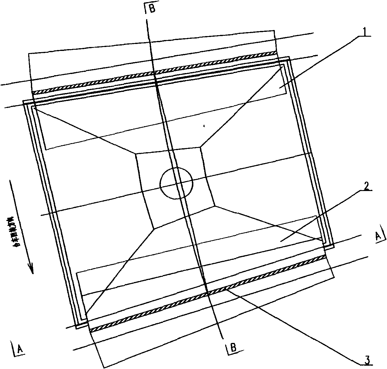
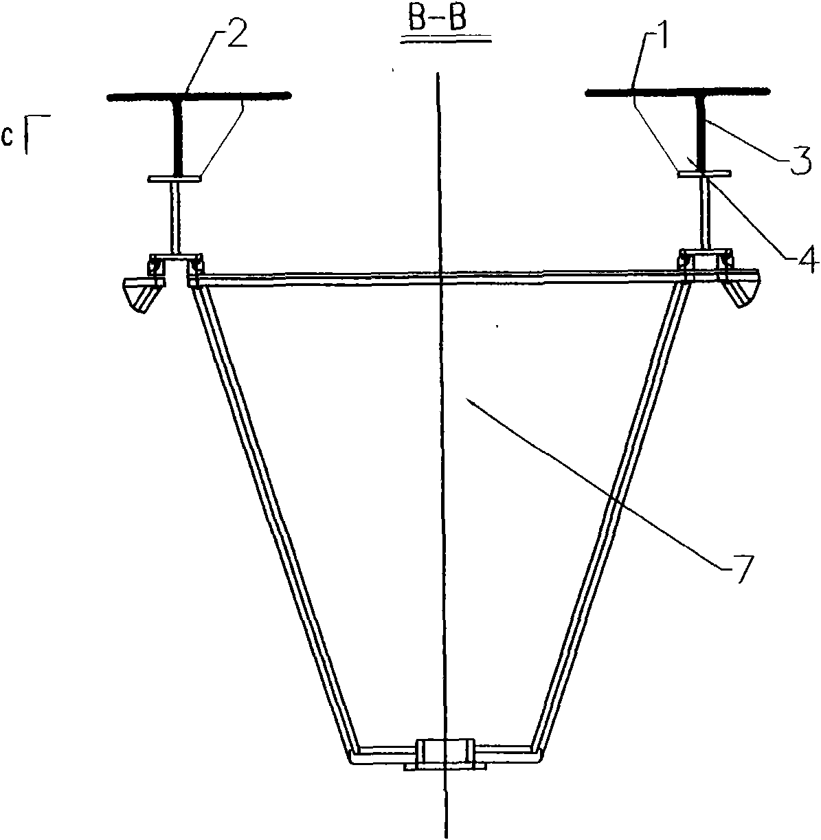
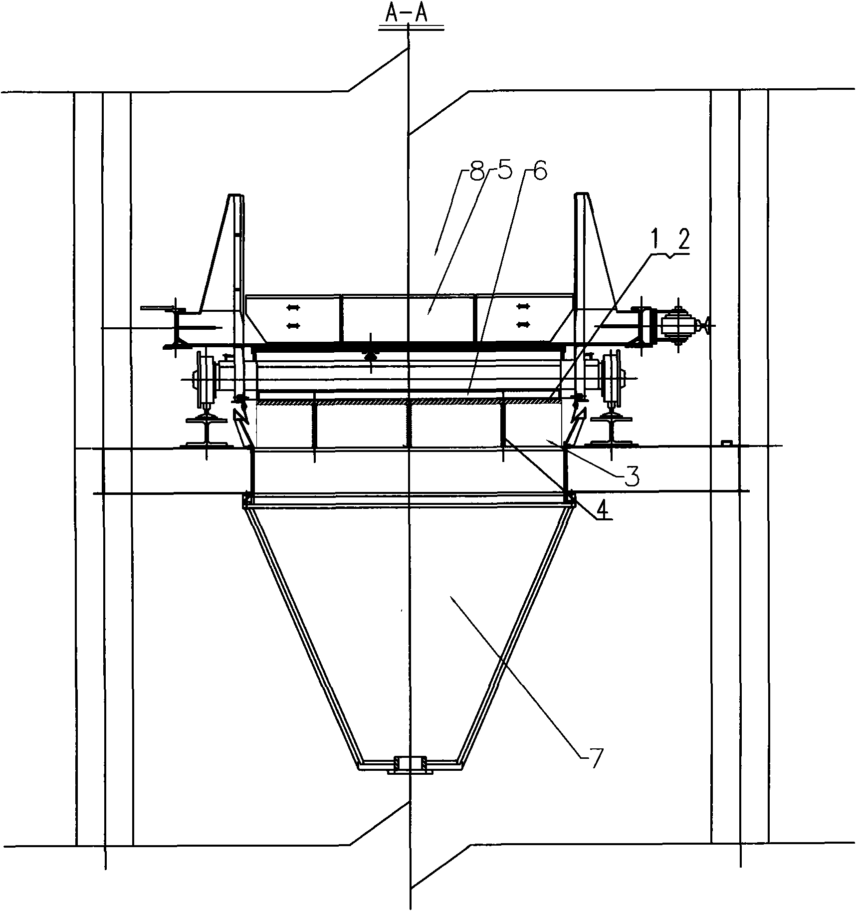
[0022] Such as Picture 1-1 , Figure 1-2 , Figure 1-3 , Figure 1-4 As shown, the end sealing structure of the air chamber of a sintering ring cooler in a steel plant designed in this embodiment includes the sealing structure of the high-temperature flue gas utilization section, the sealing structure of the low-temperature flue gas utilization section, the trolley 5 and the bottom seal of the trolley Rubber 6, the sealing structure of the high-temperature flue gas utilization section mainly includes the first horizontal sealing steel plate 1, the second horizontal sealing steel plate 2, the vertical windshield steel plate 3 and the tripod 4, the first horizontal sealing steel plate 1 and the second horizontal sealing steel plate 2 The near edge distance is less than the length between one trolley 5, and the far edge distance between the first horizontal sealing steel plate 1 and the second horizontal sealing steel plate 2 is greater than the length between two trolleys 5; ...


PUM


Abstract

The invention discloses a seal structure at the sintering ring cold machine wind chamber terminal of a steel and iron plant, which comprises a seal structure at a high-temperature smoke using section, a seal structure at a low-temperature smoke using section, a trolley and seal rubber at the bottom of the trolley, wherein the seal structure at the high-temperature smoke using section mainly comprises a first seal steel plate, a second seal steel plate, a vertical steel windproof plate and a tripod, the near-edge distance between the first seal steel plate and the second seal steel plate is shorter than the length between two sections of the trolley, and the far-edge distance between the first seal steel plate and the second seal steel plate is longer than the length between two sections of the trolley; and the invention prevents wind leaking from two terminals of a residual heat using phase in an air chamber of a smoke recycling phase so as to improve the efficiency of smoke recycle and the quality of smoke utilization, and further ensures that the whole power generating system using residual heat operates stably and effectively.

Description

technical field [0001] The present invention designs a sealing structure at the end of the air chamber of a sintering ring cooling machine trolley, especially a sealing structure for realizing efficient utilization of sintering ring cooling waste heat, reducing leakage rate, increasing flue gas recycling rate, and improving flue gas utilization quality Sealed structure. Background technique [0002] In the process of iron and steel production, the energy consumption of the sintering process accounts for about 10% of the total energy consumption, ranking second only to the iron-making process. In the total energy consumption of the sintering process, nearly 50% of the heat energy is discharged into the atmosphere in the form of sensible heat of the sintering machine flue gas and cooler exhaust gas. Because the temperature of the exhaust gas of the sintering ring cooler is not high, only 150 ~ 450 ℃, plus the limitations of the previous waste heat recovery technology, it has ...

Claims


Application Information

Patent Timeline
Patent Type & Authority Applications(China)
IPC IPC(8): F27B21/08F27D15/02
Inventor 周勇平何世民周海平
Owner ZHEJIANG XIZI UNITED ENG
Why Eureka
Try Eureka