Grinding wheel

A grinding wheel and grinding technology, which is applied in the direction of grinding machines, abrasives, grinding devices, etc., can solve the problems of reduced bending strength, poor production efficiency, hole blockage, etc., and achieve the effect of reducing the number of dressings

Inactive Publication Date: 2010-03-03
DISCO CORP
View PDF3 Cites 27 Cited by
  • Summary
  • Abstract
  • Description
  • Claims
  • Application Information

AI Technical Summary

Problems solved by technology

Although the grinding liquid or waste liquid mixed with grinding chips flows out from between the multiple grinding tools arranged in a ring by centrifugal force, a part of it will stay inside the grinding wheel, so that the grinding tools produce There is a problem of poor production efficiency due to frequent dressing of grinding tools due to hole clogging
[0011] In addition, abrasive grains such as diamond that have come off from the grinding tool are sandwiched between the wafer and the grinding tool, and in particular, only the back surface corresponding to the device region of the wafer is ground, thereby forming a ring-shaped In the wafer of the reinforced part, there is a problem that the base of the ring-shaped reinforced part is cracked and the bending strength is lowered.

Method used


Image

  • Grinding wheel
  • Grinding wheel
  • Grinding wheel

Examples


Embodiment Construction

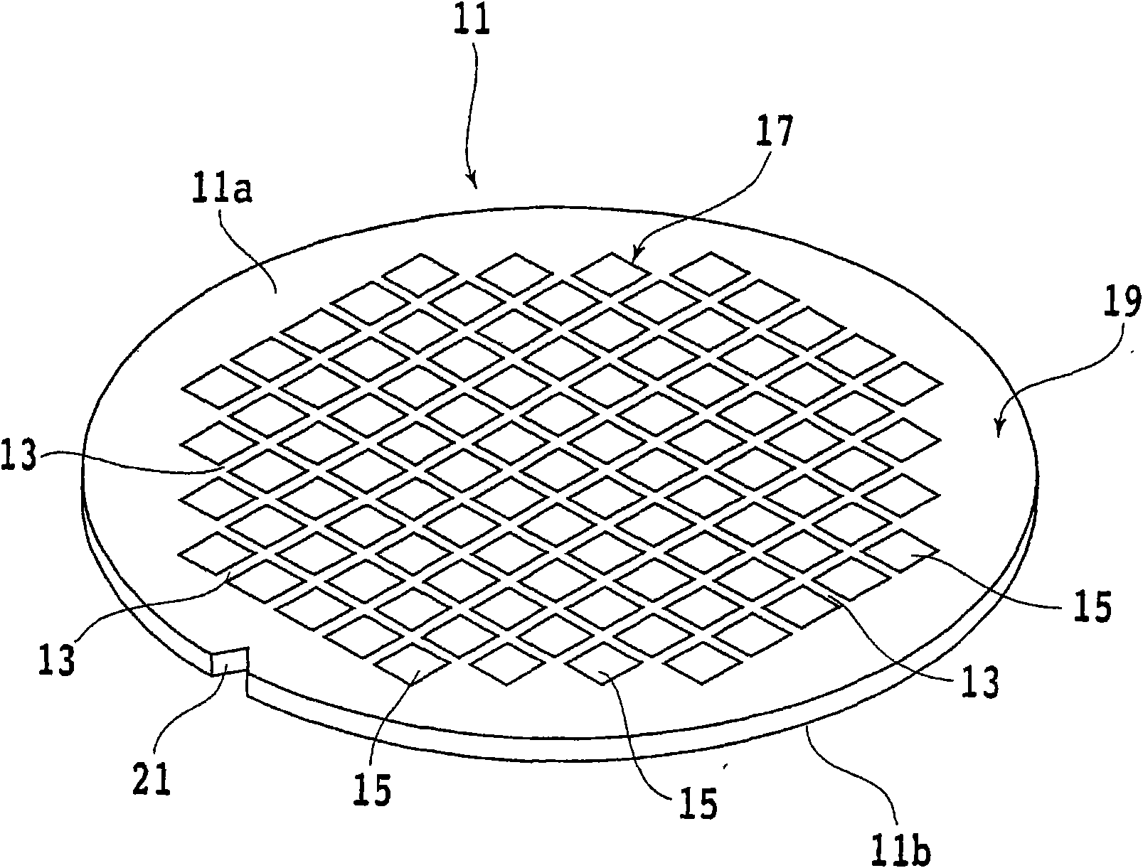
[0027] Hereinafter, a grinding wheel according to an embodiment of the present invention will be described in detail with reference to the drawings. figure 1 It is a perspective view of a semiconductor wafer before processing to a predetermined thickness. figure 1 The shown semiconductor wafer 11 is made of, for example, a silicon wafer with a thickness of 700 μm, and a plurality of partitions 13 are formed in a grid pattern on the surface 11 a, and are formed in a plurality of regions divided by the plurality of partitions 13 . There are devices 15 such as ICs and LSIs.

[0028] The thus constituted silicon wafer 11 includes: a device region 17 in which the device 15 is formed; and a peripheral remaining region 19 surrounding the device region 17 . Further, on the outer periphery of the silicon wafer 11, notches 21 are formed as marks indicating the crystal orientation of the silicon wafer.

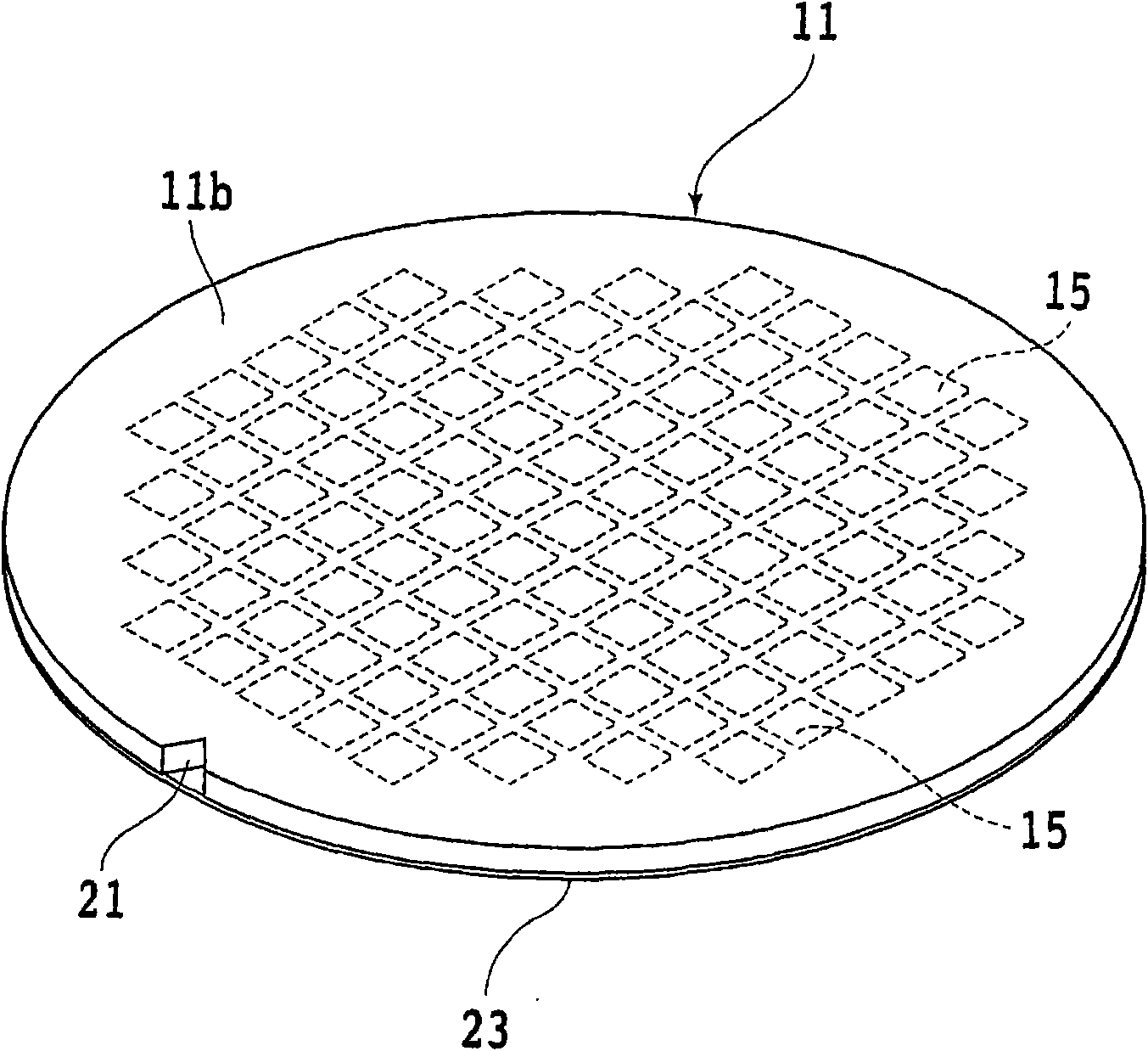
[0029] On the surface 11a of the silicon wafer 11, the protective tape 23 is paste...


PUM


Abstract

The invention provides a grinding wheel, which can decrease the finishing time of a grinding tool and prevent a wafer from generating crackles. The grinding wheel is arranged on a wheel seat of a grinding device in the free assemble and unassemble way, the grinding device comprises a grinding fluid supply member for supplying a grinding fluid, a main shaft driven to rotate and the wheel seat connected with the frontend of the main shaft. The grinding wheel is characterized in that the grinding wheel comprises an annular base with an internal wall, an external wall and an installation portion arranged on the wheel seat, and a plurality of grinding tools annularly arranged at the free end of the annular base, wherein a plurality of through holes which are spaced apart at prescribed intervalsare formed on the external wall of the annular base along the circumference direction, the plurality of through holes penetrate through the internal wall for discharging the grindstone dust and the grinding fluid.

Description

technical field [0001] The present invention relates to a grinding wheel of a grinding device having a plurality of grinding tools mounted on its free end. Background technique [0002] Regarding semiconductor wafers on which a large number of devices such as IC (Integrated Circuit) and LSI (LargeScale Integration: Large Scale Integration) are formed on the surface, and each device is divided by a predetermined dividing line (spacer), in After grinding the back surface to a predetermined thickness with a cutting device, cutting the planned dividing line with a cutting device, the semiconductor wafer is divided into individual devices, and the separated devices are used in electrical appliances such as mobile phones and personal computers. in the device. [0003] A grinding apparatus for grinding the back surface of a wafer includes: a chuck table holding a wafer; a grinding member rotatably supporting a grinding wheel provided with a grinding wheel for holding The wafer on...

Claims


Application Information

Patent Timeline
Patent Type & Authority Applications(China)
IPC IPC(8): B24B37/04B24B7/22B24B57/02H01L21/304B24B55/02B24D7/00B24D7/06B24D7/10
Inventor 山本节男
Owner DISCO CORP
Why Eureka
Try Eureka