Hollow anode ion source used for ultra high vacuum system

An anode ion source and ultra-high vacuum technology, applied in ion beam tubes, ion implantation plating, vacuum evaporation plating, etc., can solve the problems of increased film roughness, undisclosed electrical insulation, and inability to propose based on it. To achieve the effect of compact structure, small volume and cost reduction

Inactive Publication Date: 2011-09-14
HEFEI INSTITUTES OF PHYSICAL SCIENCE - CHINESE ACAD OF SCI
View PDF1 Cites 0 Cited by
  • Summary
  • Abstract
  • Description
  • Claims
  • Application Information

AI Technical Summary

Problems solved by technology

Although this kind of magnetron sputtering cathode target has the advantages of high vacuum degree and reasonable structure, it can be used in various sputtering processes such as direct current and radio frequency, and can prepare high-quality and high-purity metal or non-metal thin films, but it also has the disadvantages that are difficult to overcome. Due to the high energy of the bombardment ions, the roughness of the prepared film increases.
To solve this problem, some attempts have been made, such as "Working Principle of the Hollow-Anode Plasma Source" (Working Principle of the Hollow-Anode Plasma Source) on page 571 of Volume 4 of the journal "Ion Source Science and Technology" published in 1995. , Andr é Anders and Simone Anders, PlasmaSources Sci.Technol.4, 571 (1995)) discloses a kind of low-energy ion source based on the principle of hollow anode discharge——hollow anode ion source, which is described in detail in the article The working principle of the hollow anode ion source, and a certain theoretical fitting, although some parameters are also introduced in the paper, such as the diameter of the center nozzle hole and the gas nozzle hole are both 2mm, the thickness of the top insulating layer is 0.5mm, the ionization chamber The inner diameter of the intake pipe is 5 mm, the intake beam flow is 1 to 100 sccm / min, and the internal and external chamber pressures are on the order of 40 Pa and 0.1 Pa, etc., but the specific structure of the hollow anode ion source is not disclosed, especially for solving such as cathode ion source. The technical measures taken for the electrical insulation from other parts in the ion source, the electrical insulation and vacuum sealing when the cathode is water-cooled, and the ultra-high vacuum sealing of the ion source make it impossible for people to solve the problem based on the hollow anode discharge principle proposed by it. Low-energy ion source under ultra-high vacuum can be obtained directly

Method used


Image

  • Hollow anode ion source used for ultra high vacuum system
  • Hollow anode ion source used for ultra high vacuum system
  • Hollow anode ion source used for ultra high vacuum system

Examples


Embodiment Construction

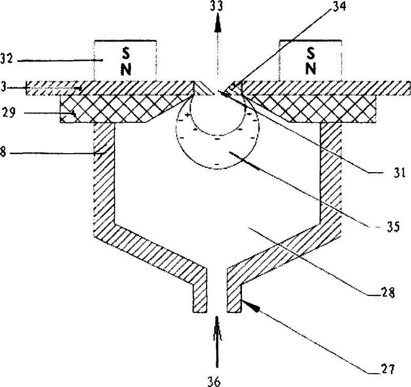
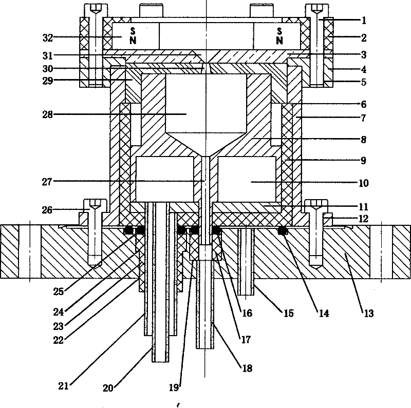
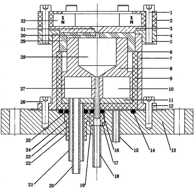
[0016] see figure 1 and figure 2 , the hollow anode ion source used in the ultra-high vacuum system includes the cathode 8 coaxially connected in series on the flange 13, the anode 3 with the central nozzle 31 and the permanent magnet 32 ​​of the outer magnet cover 2. Its specific structure is as follows:

[0017] The lower part of the cathode 8 is a water-cooled cavity 10, and the upper part is a hollow ionization chamber 28, and an insulating sleeve and a metal sleeve are sequentially set outside it; wherein, the insulating sleeve is a butt-connected insulating bottom sleeve 9 and a vent hole 30 in the center. The insulating top sleeve 29, the metal sleeve is the upper metal sleeve 4 and the lower metal sleeve 7 connected by welding, and the inner wall of the lower metal sleeve 7 is provided with a shoulder 6 which interferes with the upper surface of the insulating bottom sleeve 9. The surface of the chemical chamber 28 is covered with a titanium nitride coating (or tita...


PUM


Abstract

The invention discloses a hollow anode ion source used for an ultra high vacuum system. The lower part of a cathode (8) of the hollow anode ion source is provided with a water channel (10), and the upper part is provided with an ionization chamber (28) the outside of which is sheathed with an insulation sleeve and a metal sleeve; the lower port of the water channel (10) is provided with a cover board (11) on which an inflow pipe (20) and an outflow tube (21) are through welded; the outflow tube (21) is in insulation sealed connection with a flange (13) through a water pipe insulation sleeve (23) and a water pipe seal ring (25); the bottom of the ionization chamber (28) is communicated with an ionization chamber intake pipe (18) the lower end of which is arranged in a gas pipe hole (19); the intake pipe (18) is welded on the bottom of the gas pipe hole (19); a seal ring (14) is arranged between the insulation sleeve and the flange (13); and the upper end of the metal sleeve is fixedly connected with an anode (3), and the lower end is in butting connection with the flange (13). The hollow anode ion source generates low-energy ion beam current the energy of which is lower than 30eV under ultra high vacuum.

Description

technical field [0001] The invention relates to a hollow anode ion source, in particular to a hollow anode ion source for an ultra-high vacuum system. Background technique [0002] At present, with the rapid development of semiconductor devices, especially semiconductor integrated circuit technology, the use of magnetron sputtering to prepare metal and non-metal films such as metal electrodes and passivation films on the semiconductor surface is one of the most commonly used technical means. In order to make this technology fully implemented, people have developed corresponding equipment, such as a kind of "for Magnetron sputtering cathode target for ultra-high vacuum system". It intends to provide a reasonable structure, vacuum degree higher than 10 -6 The magnetron sputtering cathode target of Pa; its composition includes the magnet support in the shielding cover, the magnet and the water-cooling part, wherein, the water-cooling part is that the upper and lower flanges h...

Claims


Application Information

Patent Timeline
Patent Type & Authority Patents(China)
IPC IPC(8): H01J27/02C23C14/22
Inventor 徐大林邱凯李新化王玉琦曹先存尹志军罗向东
Owner HEFEI INSTITUTES OF PHYSICAL SCIENCE - CHINESE ACAD OF SCI
Why Eureka
Try Eureka