Laser machining method, laser cutting method, and method for dividing structure having multilayer board

A technology of laser processing method and cutting method, which is applied in manufacturing tools, metal processing, stone processing equipment, etc., can solve the problems of laser beam difficult to reach the lower glass plate, metal film damage, etc.

Inactive Publication Date: 2010-03-03
CHARM ENG CO LTD
View PDF4 Cites 23 Cited by
  • Summary
  • Abstract
  • Description
  • Claims
  • Application Information

AI Technical Summary

Problems solved by technology

Therefore, if there is a metal film used on the upper surface of the lower glass or the metal wiring on the back of the upper glass plate, the metal...

Method used


Image

  • Laser machining method, laser cutting method, and method for dividing structure having multilayer board
  • Laser machining method, laser cutting method, and method for dividing structure having multilayer board
  • Laser machining method, laser cutting method, and method for dividing structure having multilayer board

Examples


Embodiment 1

[0105] The laser medium is titanium sapphire crystal (center wavelength 780nm), the pulse width is 150 femtoseconds, and the output energy is above 1μJ. In addition, the object of processing was Corning Eagle 2000, which is a glass substrate, with a thickness of 700 μm. These parameters are common to all Examples unless there is a description different from this in each Example.

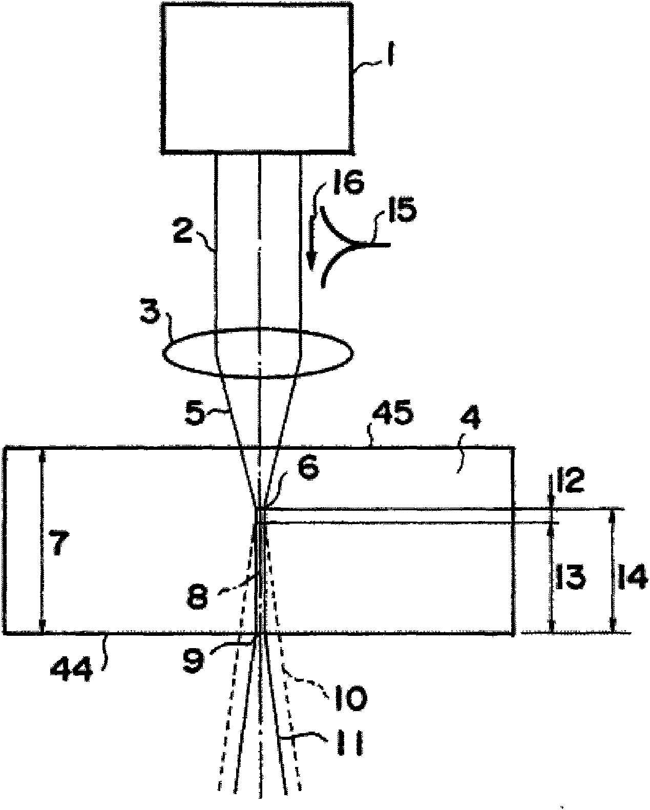
[0106] This example is figure 1 The configuration shown in is an experimental example to verify the principle of this processing method by observing changes in the object to be processed when the laser beam irradiating the object is moved from the surface to the inside.

[0107] exist Figure 10 as well as Figure 11 , shows a microscope photograph of a cross-sectional view in which changes occurring in a processed object are observed. Figure 10 shows the surface 45 of the substrate as the object to be processed, Figure 11 The vicinity of the rear face 44 is shown. for figure 1In this config...

Embodiment 2

[0110] In this embodiment, laser scanning is performed while forming the cavity channel near the back surface to form the cutting surface of the cavity channel.

[0111] In the case of filamentary cavities that form self-bunching effects, such as Figure 12 As shown in the figure inside, a funnel-shaped part 43 may be formed together on the back side. The funnel-shaped part 43 has overlapping adjacent parts, and the filamentary cavity and the channel 8 are respectively formed at the same position. By scanning the ultrashort laser pulse relatively along the back surface 44 of the object to be processed, the depth of processing along the scanning direction can be reduced. A plurality of filamentary cavities juxtaposed are formed on the winding wire 46 . exist Figure 12 The middle control shows a photomicrograph of the cut surface of the thus formed filamentary cavities. In this example, after scanning with laser pulses at a scanning speed of 3 mm / s, the section was observed ...

Embodiment 3

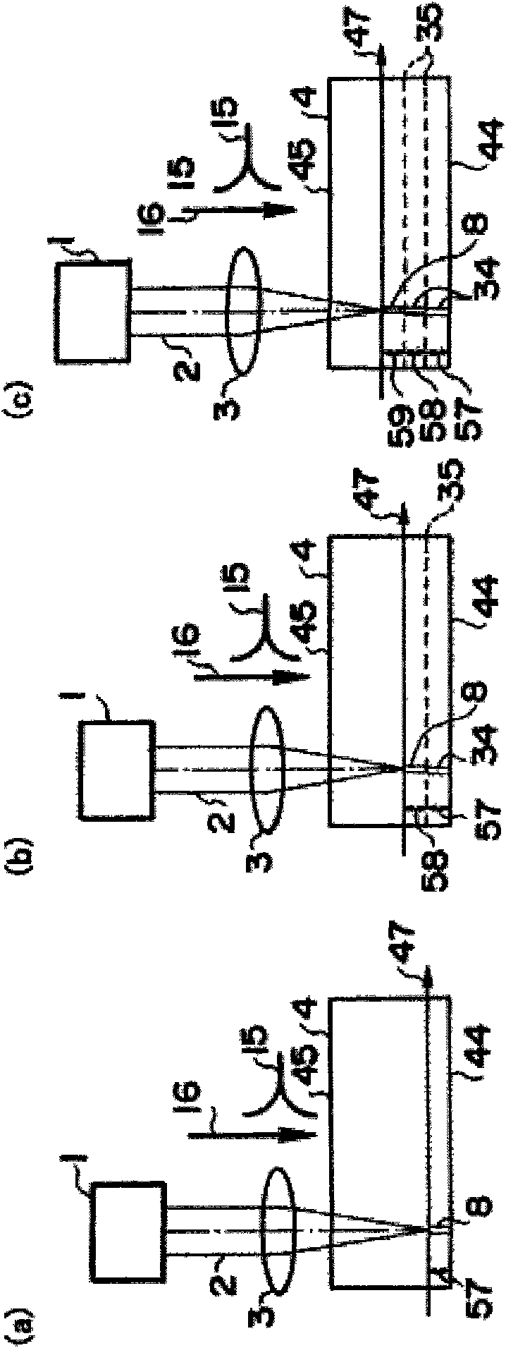
[0113] by image 3 In the configuration shown in , the height of the beam waist is changed, multiple scans are performed, and the vicinity of the back side is processed. Figure 15 The cross section in the case where the number of scans is 4, the pulse energy is 10 μJ, and the pulse width is 2 ps is shown. By reducing the pulse energy and optimizing the pulse width, a high-quality processed region 36 can be formed near the back surface.


PUM

PropertyMeasurementUnit
Pulse widthaaaaaaaaaa
Wavelengthaaaaaaaaaa

Abstract

The present invention provides a method for efficiently machining a work with a very short pulse. A method is used for machining a work such as a board with a laser beam. The method is characterized in that a very short pulse laser beam having a wavelength to which the work is transparent is directed to the front surface of the work toward the back surface and focused, the beam waist of the focused laser beam is located away from the back surface of the work, a beam focus channel long in the light beam traveling direction from the beam waist formed by the auto-focusing action due to the laserbeam propagation in the work is thus formed in the work, a substance in the channel is decomposed by the laser beam, the decomposed substance can be discharged from the back surface, and a cavity is formed in the channel. While forming the cavity, the laser beam is scanned, a machined surface is formed, and thereafter the work can be cut with a weak bending stress. The invention can be applied todivide two substrates opposed to each other, and can be used for dividing a glass substrate of a liquid crystal panel.

Description

technical field [0001] The present invention relates to a method for efficiently and high-quality processing of an object to be processed, particularly a flat object such as a substrate, using an ultrashort pulse laser having a wavelength transparent to the object. [0002] The present invention also relates to a method for dividing a structure having a multilayer substrate by using a laser, wherein the multilayer substrate has a structure in which at least two substrates are arranged in parallel with spacers interposed therebetween. The present invention is suitable for dividing flat display panels using glass substrates such as liquid crystal display panels and plasma display panels. Background technique [0003] In the electronics industry, the miniaturization of semiconductor devices such as CPUs, DRAMs, and SRAMs has progressed year by year, and at the same time, high integration of internal circuits has been achieved. The structures of these devices are formed with hi...

Claims


Application Information

Patent Timeline
IPC IPC(8): B23K26/06B23K26/00B23K26/38B23K26/40B28D5/00B23K101/40
CPCB23K26/0054B23K26/0063B23K26/4075B23K26/006B23K2201/40B23K26/40B23K26/389B23K26/55B23K26/57B23K2101/40B23K2103/50B28D5/00B23K26/0622B23K26/382
Inventor 镰田将尚住吉哲实辻川晋关田仁志
Owner CHARM ENG CO LTD
Why Eureka
Try Eureka