Copper-base powder metallurgy clutch friction body

A powder metallurgy, clutch technology, applied in the direction of friction lining, mechanical equipment, etc., can solve the problems of shear resistance, low compressive strength, large wear, uneconomical, etc., and achieve good thermal stability, stable friction coefficient, and service life. long effect

Inactive Publication Date: 2012-01-04
重庆江洲粉末冶金科技有限公司
View PDF0 Cites 0 Cited by
  • Summary
  • Abstract
  • Description
  • Claims
  • Application Information

AI Technical Summary

Problems solved by technology

However, the existing friction materials, such as copper-based powder metallurgy friction materials such as FM-103G and FM-105G, have a friction coefficient of only about 0.15-0.2 under heavy load conditions such as rail cars, and have low shear and compressive strengths. , the wear is also large, and it cannot meet the requirements of railway rail cars, and its price is relatively high, which is not economical

Method used


Image

  • Copper-base powder metallurgy clutch friction body
  • Copper-base powder metallurgy clutch friction body
  • Copper-base powder metallurgy clutch friction body

Examples


Embodiment 1

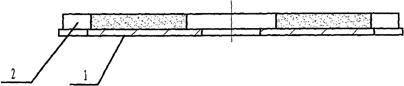
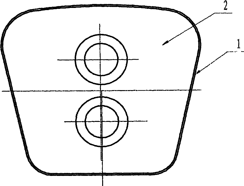
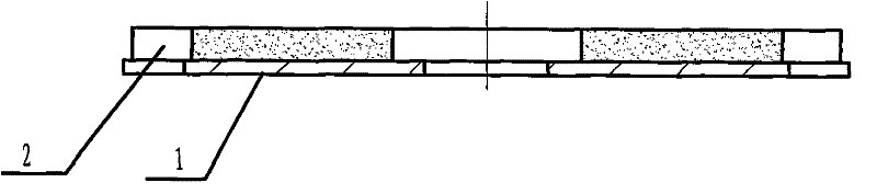
[0034] Embodiment 1: The first copper-based powder metallurgy clutch friction body, see figure 1 with figure 2 A piece of copper-based powder metallurgy friction plate 2 is stacked on the steel core plate 1, and sintered into one under pressure; the composition and specifications of the copper-based powder metallurgy friction plate 2 are shown in Table 1

[0035] Table 1

[0036]

[0037]Note: ※ is a batch of graphite powder, and its batch ratio is: -60~+100 mesh accounts for 75%; -100~+140 mesh accounts for 15%; -200 mesh accounts for 10%; Cu·Fe is copper clad iron composite Powder, its patent number is: ZL031178634, executive standard: Q / CYZ.6-2001.

[0038] The manufacturing process of the first copper-based powder metallurgy clutch friction body is as follows:

[0039] The first step is to prepare materials according to the above formula → batching → mixing → pressing to obtain copper-based powder metallurgy friction plate 2; the pressing process is carried out on Y...

Embodiment 2

[0047] Embodiment 2: The second copper-based powder metallurgy clutch friction body, see figure 1 with figure 2 A piece of copper-based powder metallurgy friction plate 2 is stacked on the steel core plate 1, and sintered into one under pressure; the composition and specifications of the copper-based powder metallurgy friction plate 2 are shown in Table 2.

[0048] Table 2

[0049]

[0050] Note: ※ is a batch of graphite powder, and its batch ratio is: -60~+100 mesh accounts for 75%; -100~+140 mesh accounts for 15%; -200 mesh accounts for 10%; Cu·Fe is copper clad iron composite Powder, its patent number is: ZL031178634, executive standard: Q / CYZ.6-2001.

[0051] The manufacturing process of the second copper-based powder metallurgy clutch friction body is as follows:

[0052] The first step is to prepare materials according to the above formula → batching → mixing → pressing to obtain copper-based powder metallurgy friction plate 2. The pressing process is carried out ...


PUM

PropertyMeasurementUnit
densityaaaaaaaaaa
hardnessaaaaaaaaaa
friction coefficientaaaaaaaaaa

Abstract

The invention relates to a copper-base powder metallurgy clutch friction body which comprises a steel core plate, and is characterized in that: a copper-base powder metallurgy friction piece is arranged on the steel core plate in an overlapped way, and the copper-base powder metallurgy friction piece and the steel core plate are sintered into a whole under pressurization. The copper-base powder metallurgy friction piece comprises the following components by weight percent: 12-14% of copper-coated iron composite powder, 5-7% of Sn, 2-4% of Pb, 1-3% of Zn, 8-10% of blending graphite powder, 3-5% of SiC, 5-7% of ZrO2.SiO2 (zircon sand) ( or 5-7% of 3Al2O3.2SiO2 (mullite) ) and the balance of Cu; and additives comprise: zinc stearate accounting for 0.8% of the total content and machine oil accounting for 0.3% of the total content. The copper-base powder metallurgy clutch friction body has good clutch braking capability, soft and stable connection and arrangement, and is safe and reliable,not only solves the technical problems of producing the clutch friction body of a railway track locomotive, but also is used for producing and manufacturing clutch dry-type friction braking elements needed by large-scale overload automobiles, engineering metal forming machinery and the like.

Description

technical field [0001] The invention relates to a clutch assembly, in particular to a copper-based powder metallurgy clutch friction body. Background technique [0002] The clutch driven friction disc assembly of the rail locomotive (JZM-03) is a key component of the rail locomotive clutch used in each locomotive depot of the railway system. It plays the role of moving forward, stopping and retreating the rail car, and is an indispensable and important part of the clutch of the rail car. There are 2 clutch driven friction disc assemblies and 1 middle pressure plate in each rail car clutch, plus the left and right end cover plates to form four friction pairs. Among them, the rail locomotive clutch driven friction disc assembly is composed of 12 clutch friction bodies, 1 clutch steel chip, 8 large and small damping springs, 1 flower disc, 1 spline tooth disc, 2 cover plates, and 10 A flat head rivet and 8 countersunk rivets are assembled by riveting a total of 61 parts. Eac...

Claims


Application Information

Patent Timeline
Patent Type & Authority Patents(China)
IPC IPC(8): F16D69/00F16D69/02B22F3/16
Inventor 向兴碧赖绍楷侯开太唐开祥郭江马铁骊
Owner 重庆江洲粉末冶金科技有限公司
Why Eureka
Try Eureka