Steel-sleeve steel steam insulation pipe and rolling supporting mechanism thereof

A technology of rolling support and thermal insulation pipeline

Inactive Publication Date: 2010-03-10
刘毅 +1
View PDF0 Cites 6 Cited by
  • Summary
  • Abstract
  • Description
  • Claims
  • Application Information

AI Technical Summary

Problems solved by technology

Due to the high temperature of the steam, the deformation of the inner steel pipe is relatively large, which causes the inner steel pipe to float up and down or drift left and right inside the outer steel pipe.

Method used


Image

  • Steel-sleeve steel steam insulation pipe and rolling supporting mechanism thereof
  • Steel-sleeve steel steam insulation pipe and rolling supporting mechanism thereof
  • Steel-sleeve steel steam insulation pipe and rolling supporting mechanism thereof

Examples


Embodiment 1

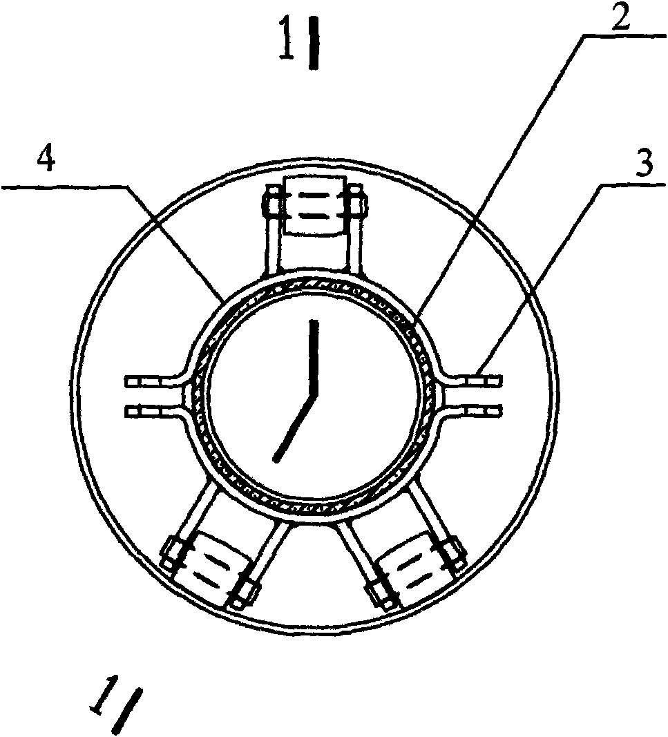
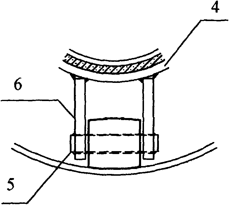
[0021] control Figure 1-4 , to illustrate the specific technical solutions of the present invention. In this embodiment, the steel jacketed steel steam insulation pipeline includes: an inner sleeve steel pipe with a diameter of 219 mm; The thickness of the material is 9 mm (high-strength heat-resistant asbestos rubber); the rolling support mechanism located between the outer heat insulation material and the outer steel pipe; The insulation material is ultra-fine glass wool tube shell, which is wrapped with double-layer staggered seams. The outer diameter of the insulation layer is smaller than the inner diameter of the jacket steel pipe, and an air layer is formed between the two; Air valve, through the exhaust valve, the air layer can be converted into a vacuum layer; the anti-corrosion layer (3PE) is set on the outer steel pipe. The rolling support mechanism includes:

[0022] The upper steel hoop and the lower steel hoop bent into the outer circle of the inner sleeve st...

Embodiment 2

[0026] In this embodiment, the steel jacketed steel steam insulation pipeline includes: an inner sleeve steel pipe with a diameter of 108 mm; The thickness of the thermal material is 6 mm (high-strength heat-resistant asbestos rubber); the rolling support mechanism located between the outer heat insulation material and the outer steel pipe; Insulation material, the insulation material is an ultra-fine glass wool tube shell, which is wrapped with double-layer staggered seams. The outer diameter of the insulation layer is smaller than the inner diameter of the jacket steel pipe, and an air layer is formed between the two; it is located on the jacket steel pipe and communicated with the air layer Exhaust valve, through the exhaust valve, the air layer can be converted into a vacuum layer; the anti-corrosion layer (3PE) is set outside the jacket steel pipe. The rolling support mechanism includes:

[0027] The upper steel hoop and the lower steel hoop bent into the outer circle of...


PUM

PropertyMeasurementUnit
Nominal diameteraaaaaaaaaa

Abstract

The invention relates to a steel-sleeve steel steam insulation pipe and a rolling supporting mechanism thereof, wherein the nominal diameter of an inner sleeve steel pipe of the steel-sleeve steel steam insulation pipe is DN 150-DN 200. The rolling supporting mechanism comprises an upper steel hoop, a lower steel hoop, one upper idler wheel arranged at the right center of the upper steel hoop, andtwo lower idler wheels arranged on the lower steel hoop and distributed symmetrically, wherein the end parts of the upper steel hoop and the lower steel hoop are clamped tightly by bolts; and when the axes of the inner sleeve steel pipe and an outer sleeve steel pipe are overlapped, the two lower idler wheels and the inner wall of the outer sleeve steel pipe are contacted in a rolling friction way, and a fit-up gap is left between the upper idler wheel and the inner wall of the outer sleeve steel pipe. The steel-sleeve steel steam insulation pipe comprises the inner sleeve steel pipe and theouter inner sleeve steel pipe, and also comprises the rolling supporting mechanism, insulation material, heat-preservation material, an air evaporation valve and erosion resistant coating. The rollingsupporting mechanism has small friction force, therefore, the stress of the rolling supporting mechanism and the inner sleeve steel pipe is reduced.

Description

technical field [0001] The invention relates to a heat-insulating steam delivery pipeline, and further relates to a steel-sheathed steel steam insulation pipeline with a nominal diameter of inner steel pipes of DN150-DN200 and a rolling support mechanism thereof. Background technique [0002] Steel-sheathed steel steam insulation pipeline is a new technology developed in recent years, which is used to transport high-temperature steam (250-350°C). Its structure basically includes an inner steel pipe and an outer steel pipe, and some insulation materials are filled in the middle. Due to the high temperature of the steam, the deformation of the inner steel pipe is relatively large, which causes the inner steel pipe to float up and down or drift left and right inside the outer steel pipe. The general insulation material is difficult to withstand the deformation caused by such a high temperature, resulting in the destruction of the insulation layer. and the difficult problem of ...

Claims


Application Information

Patent Timeline
IPC IPC(8): F16L59/135F16L3/16F16L59/147F16L59/04F16L59/065F16L58/10
Inventor 刘毅朱秀红
Owner 刘毅
Why Eureka
Try Eureka