Membrane integrated microtrip ferrite circulator

A technology of ferrite and circulators, applied in waveguide devices, electrical components, circuits, etc., can solve the problems of small effective permeability tensor k/μ, unfavorable microwave circuit integration, etc., to reduce volume and facilitate Integrate and promote the effect of development

Inactive Publication Date: 2010-03-10
UNIV OF ELECTRONICS SCI & TECH OF CHINA
View PDF0 Cites 21 Cited by
  • Summary
  • Abstract
  • Description
  • Claims
  • Application Information

AI Technical Summary

Problems solved by technology

[0005] The solution of the present invention is based on the basic structure of the traditional microstrip microwave circulator, aiming at the proportion of ferrite in the structure made of substrate and ferrite diaphragm under the same thickness is often very small, resulting in The effective permeability tensor k / μ is small, and the proportion of ferrite in the structure is increased by increasing the thickness of the ferrite diaphragm, and the effective permeability tensor k / μ is effectively improved. , the thickness (volume) of the structure will also increase significantly, which is not conducive to the integration of microwave circuits.

Method used


Image

  • Membrane integrated microtrip ferrite circulator
  • Membrane integrated microtrip ferrite circulator
  • Membrane integrated microtrip ferrite circulator

Examples


Embodiment 1

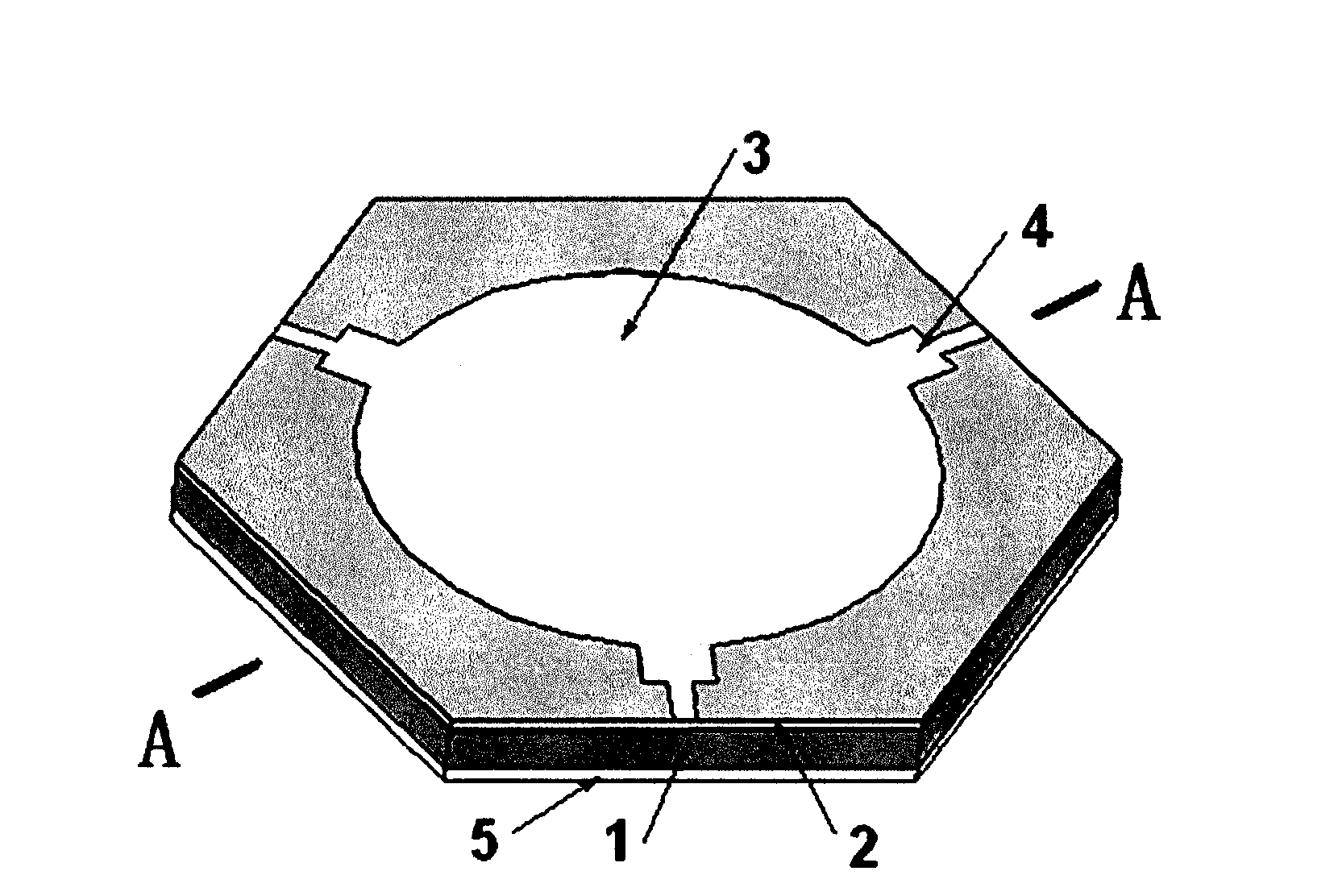
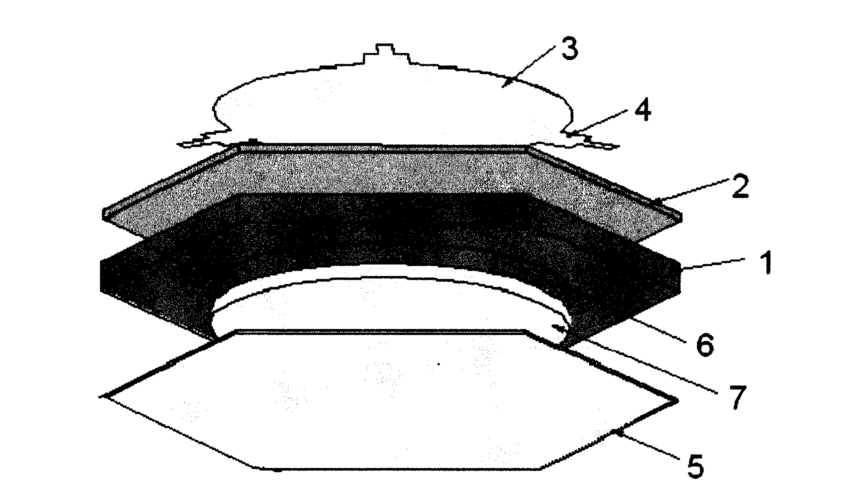
[0013] Example 1: figure 2 .It is a schematic diagram of the unfolded state of each part of the circulator in this embodiment, and the substrate 1 is made of Al 2 o 3 Ceramic material, its thickness is 200μm (micron), relative permittivity is 9.8; its bottom groove 6 radius R880μm, groove depth 150μm,; ferrite diaphragm 2 is barium ferrite, thickness is 10μm, saturation magnetization It is 2500Gs, the relative permittivity is 15, and the bias magnetic field received by the ferrite film is 10 6 A / m; the central junction 3, the matching section 4, and the grounding film 5 are all gold (Au) films with a thickness of 3 μm. The widths and lengths of the two-node wires with narrow outer ends are 400 μm, 200 μm, 160 μm, and 940 μm, respectively; the high-conductivity metal block 7 is made of silver (Ag), and its radius is the same as that of the central junction 3, which is also 880 μm , and its thickness is 150 microns.

[0014] The manufacturing method of the circulator in thi...

Embodiment 2

[0016] Example 2: Figure 4 .It is a schematic diagram of the structure of the present embodiment 2. The substrate 1 and its groove 6, the ferrite diaphragm 2, the central junction 3, and the matching section 4 are all the same as those of the embodiment 1. In this embodiment, the bottom surface of the substrate 1 and the concave A gold film with a thickness of 3 μm is evaporated on the inner surface of the groove 6, and the metal block (Ag) 7 is omitted to save some precious metals and further reduce the weight.


PUM

PropertyMeasurementUnit
thicknessaaaaaaaaaa
thicknessaaaaaaaaaa
radiusaaaaaaaaaa

Abstract

The invention belongs to an integrated microtrip ferrite circulator in solid electronic devices, comprising a dielectric or a semiconductor substrate, a high-conductivity metal block or an earthing membrane, a ferrite membrane, a high-conductivity centre junction, a matching section of the high-conductivity centre junction and a high-conductivity earthing membrane, wherein, the dielectric is provided with a groove at the bottom; the high-conductivity metal block is arranged in the groove; the ferrite membrane is adhered above the substrate; the high-conductivity centre junction tightly clingsto the ferrite membrane; the high-conductivity earthing membrane is positioned on the bottom surface of the substrate. The circulator is additionally provided with a groove at the bottom surface of the substrate, a metal block is arranged in the groove, wherein, the volume of the metal block is the same as that of the groove, or an earthing membrane is covered on the internal surface of the groove, so that the effective permeability tensor k / mu is greatly improved, while the impedance is greatly reduced; on the premise of the same performance and compared with the background technology, the volume and thickness of the circulator can be effectively reduced; on the premise that the performance and the reliability of the ferrite circulator are ensured, the volume and thickness of the circulator can be effectively reduced; miniaturization, planarity and the convenient integration of microwave circuits are realized, thus the development of monolithic microwave integrated circuit is promoted.

Description

technical field [0001] The invention belongs to the technical field of microwave device production in solid electronic devices, in particular to a microstrip ferrite circulator integrated with diaphragm ferrite. Background technique [0002] Ferrite circulator is a non-reciprocal multi-port microwave device, which has the characteristics of transmitting microwave signals in a specific direction and isolating in the opposite direction; it is used in microwave communication, electronic countermeasures, microwave measurement, phased array radar T / R components and other systems play an important role. For example, in the base station and mobile system of mobile communication, the ferrite circulator is mainly used as a shared device connected to the receiving and transmitting circuit and the antenna; in the transmitting and receiving system, it is used as the input and output isolation of the power amplifier and switching amplifier and in the measurement system It plays a decou...

Claims


Application Information

Patent Timeline
Patent Type & Authority Applications(China)
IPC IPC(8): H01P1/387
Inventor 彭斌张万里汪渊张文旭蒋洪川
Owner UNIV OF ELECTRONICS SCI & TECH OF CHINA
Why Eureka
Try Eureka