Self-adaptive driving circuit of active clamping switch tube

A drive circuit and clamp switch technology, which is applied in the direction of conversion equipment with intermediate conversion to AC, can solve problems such as increased faults and power loss, complex drive circuits, and difficult implementation of Td, and achieves reduced turn-off losses and simple circuits , low cost effect

Active Publication Date: 2010-03-10
TEN PAO ELECTRONICS HUIZHOU
View PDF0 Cites 12 Cited by
  • Summary
  • Abstract
  • Description
  • Claims
  • Application Information

AI Technical Summary

Problems solved by technology

like Image 6 The dead time Tr shown is relatively easy to realize, only need to detect the turn-off signal of the main switch tube and then delay the Tr time through the RC circuit to output positive pulses to drive the clamp switch to be turned on, as shown in Image 6 It is quite difficult to realize the dead time Td shown, because in general, the turning off of the drive pulse of the clamp switch needs to detect the moment when the energy of the transformer is completely discharged, otherwise the clamp switch cannot judge when to turn off. Affected by the input capacitance and switching speed of the clamp switch, there will be a delay in the turn-off of the clamp switch. At this time, the main switch tube may have already been turned on, and there will be a common phenomenon between the two switch tubes, which will lead to failure and power failure. Loss increase
Therefore, it will be more complicated and difficult to design the driving circuit of the active clamp switch. So far, no mature commercial integrated circuit has been seen to realize the active clamp function in the flyback quasi-resonant mode.

Method used


Image

  • Self-adaptive driving circuit of active clamping switch tube
  • Self-adaptive driving circuit of active clamping switch tube
  • Self-adaptive driving circuit of active clamping switch tube

Examples


Embodiment Construction

[0025] In order to facilitate the understanding of those skilled in the art, the present invention will be further described in detail below in conjunction with specific embodiments and accompanying drawings.

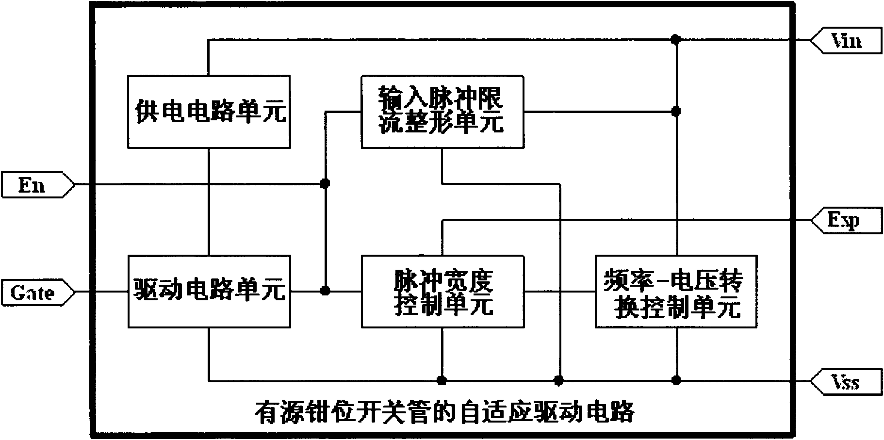
[0026] Such as figure 1 As shown, the adaptive drive circuit of the active clamp switch tube is used to drive the clamp switch tube in the switching power supply of the flyback quasi-resonant control mode to realize the active clamp function, and the circuit specifically includes: mutual electrical connection The drive circuit unit, the frequency-voltage conversion control unit, the pulse width control unit, the input pulse current limiting shaping unit and the power supply circuit unit.

[0027] The above-mentioned units form a circuit module, which includes at least three necessary ports, namely Vin, Gate and Vss, which can be conveniently applied to switching power supplies. Among them, Vin and Vss are respectively connected to both ends of the active clamp signal ...


PUM


Abstract

The invention relates to a self-adaptive driving circuit of an active clamping switch tube in the field of switch power supply. The circuit input terminal Vin and Vss are connected with two ends of anactive clamping signal detection winding Nf of a transformer; the output terminal Gate is connected with the control terminal of the active clamping switch tube; the self-adaptive driving circuit comprises a frequency-voltage conversion control unit, a pulse width control unit, an input pulse current-limiting and shaping unit, a driving circuit unit and a power supply circuit unit that are electrically connected with one another; and the circuit can be also provided with an enabling port and an extended function port. In the invention, the circuit is brief, the cost is low, the circuit is applied to a switch power converter of a flyback quasi-resonant mode and can realize the voltage clamping function; the voltage stress of a main switch tube can be reduced, the electromagnetic noise of the power supply can be reduced, the electromagnetic compatibility characteristic of the power supply can be improved; simultaneously the loss of the clamping circuit can be reduced, the efficiency ofthe power supply can be improved, and the performances of the switch power converter of the flyback quasi-resonant mode are obviously improved.

Description

technical field [0001] The invention relates to the field of switching power supplies, in particular to an adaptive drive control circuit for driving a clamp switch tube to realize an active clamp function in an active clamp circuit of a switch power supply adopting a flyback quasi-resonant control mode . Background technique [0002] Flyback quasi-resonant mode switching power converters can be widely used in small and medium power switching power converters due to their simple circuit topology, zero-voltage turn-on of switching tubes, low loss, low noise, and good electromagnetic compatibility characteristics. Popular, however, the voltage and current stress of the power switching tube of the flyback quasi-resonant mode converter is large, and the voltage ringing peak of the switching tube caused by leakage inductance is shown in figure 2 As shown, the point indicated by the arrow in the figure is the switch tube spike caused by the leakage inductance. This voltage ringin...

Claims


Application Information

Patent Timeline
Patent Type & Authority Applications(China)
IPC IPC(8): H02M3/28
Inventor 洪光岱
Owner TEN PAO ELECTRONICS HUIZHOU
Why Eureka
Try Eureka