Ion sources and methods of operating an electromagnet of an ion source

An ion source, electromagnet technology, applied in the field of ion beam

Active Publication Date: 2010-03-24
VEECO INSTR
View PDF2 Cites 20 Cited by
  • Summary
  • Abstract
  • Description
  • Claims
  • Application Information

AI Technical Summary

Problems solved by technology

It is not easy to change the transparency of the grid lens to compensate for the dependence on the operating state

Method used


Image

  • Ion sources and methods of operating an electromagnet of an ion source
  • Ion sources and methods of operating an electromagnet of an ion source
  • Ion sources and methods of operating an electromagnet of an ion source

Examples


example 1

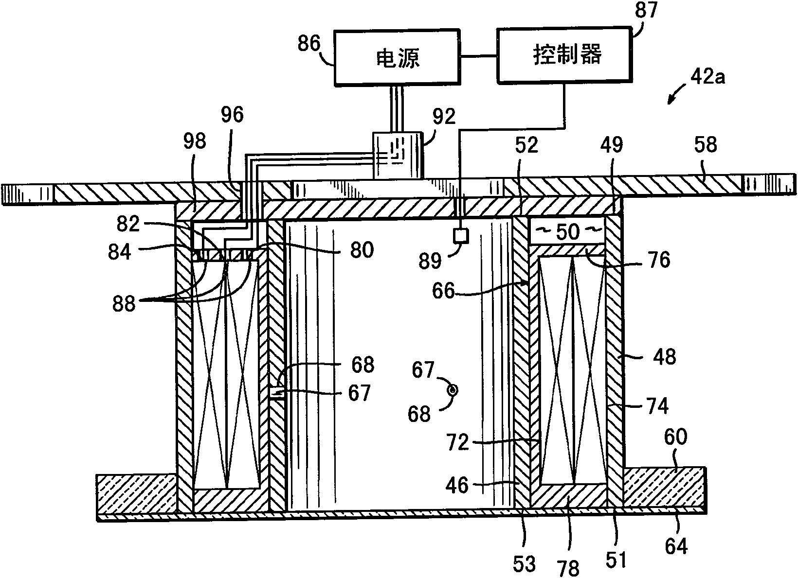
[0088] Ion source with electromagnet assembly, otherwise substantially the same as electromagnet 42b ( Image 6 ) is the same, but with each of the inner and outer coils comprising a single coil of 970 turns, in order to measure the current supplied to the radially outermost coil of the electromagnet 42b, between the radially innermost coil of the electromagnet and the power supply The room is equipped with an ammeter. The coils of the radially outermost electromagnets are disconnected from the power source so that only the innermost coils of the electromagnet 42b are energized. An electrical probe is inserted into the beam and placed in the plane of the substrate perpendicular to the direction of incidence of the beam. The voltage of the electrical probes, which are charged under the substrate processing conditions, is measured. This voltage is considered to be a measurement of neutralizing the broad ion beam.

[0089] A 1200V, 650mA positively charged ion beam was extract...

example 2

[0096] As evidence that the electromagnets were operated under controlled conditions without reducing the directivity of the ion beam, the "local divergence angle" of the angular distribution of the ions was evaluated for optimal electromagnet current settings for different locations in the beam and compared to the same Equivalent results obtained without electromagnets at process parameters are compared. The "local divergence angle" is determined by etching the substrate under the shield aperture and measuring the size of the etched spot, essentially as in J.R.Kahn, et al. in J.Vac.Sci.Technol.A14(4), Jul / Aug 1996, p. 2106-2112 pages (reference figure 1 ), in addition to using a silicon oxide-coated silicon wafer as a substrate, and using a nanospectrophotometer (Nanometrics Nanospec) with high-resolution etch depth and lateral position measurements TM 8000) to determine the etch depth profile. The entire disclosure of this publication is incorporated herein by reference. ...

example 3

[0101] A series of ion etch profiles, normalized for display, were generated using the ion source and operating parameters of Example 1 (except for the current applied to the electromagnet), and as Figure 9 shown. With no current applied to the coils of the electromagnet (and thus no field strength), the plasma density distribution and plasma ion flux distribution are characterized by a convex profile, which is reflected in the ion etch profile 200 . at relatively low field strengths B L , the convexity of the plasma density distribution and the plasma ion flux distribution increases with increasing field strength, as shown by the ion etch profile 210 . at relatively high field strengths B H , the plasma density distribution and the plasma ion flux distribution change shape to become more concave as the field strength increases. Finally, the plasma density distribution and plasma ion flux distribution become concave, as shown by the ion etch profile 220 .

[0102] at rela...


PUM


Abstract

Ion sources and methods of operating an electromagnet of an ion source for generating an ion beam with a controllable ion current density distribution. The ion source (10) includes a discharge chamber (16) and an electromagnet (42; 42a-d) adapted to generate a magnetic field (75) for changing a plasma density distribution inside the discharge chamber (16). The methods may include generating plasma (17) in the discharge space (24), generating and shaping a magnetic field (75) in the discharge space (24) by applying a current to an electromagnet (42; 42a-d) that is effective to define the plasma density distribution, extracting an ion beam (15) from the plasma (17), measuring a distribution profile for the ion beam density, and comparing the actual distribution profile with a desired distribution profile for the ion beam density. Based upon the comparison, the current applied to the electromagnet (42; 42a-d) may be adjusted to modify magnetic field (75) the magnetic field in the discharge space and, thereby, alter the plasma density distribution.

Description

[0001] CROSS-REFERENCE TO RELATED APPLICATIONS [0002] This application is a continuation-in-part of US Patent Application No. 11 / 678,979, filed February 26, 2007, which is a continuation-in-part of US Patent No. 10 / 772,132, filed February 4, 2004, now US Patent No. 7,183,716 Continued in part, the disclosures of each are hereby incorporated by reference in their entirety. This application claims priority to US Provisional Application Np. 60 / 891,669, filed February 26, 2007, the disclosure of which is incorporated herein by reference. technical field [0003] The present invention relates to an ion source and a method for operating an electromagnet of the ion source to generate an ion beam with tailored operating characteristics. Background technique [0004] Ion beam processing systems are used in a variety of applications for adjusting the properties of substrates during the fabrication of thin film devices such as semiconductors and data storage devices. Specifically, ...

Claims


Application Information

Patent Timeline
Patent Type & Authority Applications(China)
IPC IPC(8): H01J37/08H01J27/18H01J27/16H01J37/32C23C14/35
CPCH01J2237/24542H01J37/305H01J27/18H01J37/08H01J37/302H01J2237/0656H01J37/32082
Inventor A·V·海斯R·叶夫图霍夫V·卡纳罗夫B·L·德吕
Owner VEECO INSTR
Why Eureka
Try Eureka