Spin microwave oscillator and spin microwave detector

A technology of detectors and oscillators, applied in resonators, waveguide devices, instruments, etc., can solve the problems of narrow frequency modulation range, difficult integration, difficult frequency modulation, etc., and achieve simplified device structure and process, high frequency controllable and tunable performance, improve the effect of radiation resistance

Active Publication Date: 2010-03-31
INST OF PHYSICS - CHINESE ACAD OF SCI
View PDF2 Cites 19 Cited by
  • Summary
  • Abstract
  • Description
  • Claims
  • Application Information

AI Technical Summary

Problems solved by technology

For example, the magnetron oscillator was applied relatively early, but it is too large, not easy to integrate, and has a low frequency and high power consumption, so it cannot be used for future communications; the frequency of the LC voltage-controlled oscillator is not high, almost It cannot reach gigahertz, and the frequency modulation range is relatively narrow, the integration level is low, and the quality factor is also low; the output frequency of crystal oscillators generally does not exceed 200MHz. Although the frequency stability is relatively good, frequency modulation is more difficult.
[0003] In terms of microwave detectors, there are also some shortcomings at present, such as large volume, high power consumption, low frequency that can be detected, low measurement accuracy of ultra-high frequency, and high-frequency signals that cannot be directly measured must be mixed. Disadvantages such as reducing high-frequency signals to low-frequency signals for measurement

Method used


Image

  • Spin microwave oscillator and spin microwave detector
  • Spin microwave oscillator and spin microwave detector
  • Spin microwave oscillator and spin microwave detector

Examples


Embodiment 1

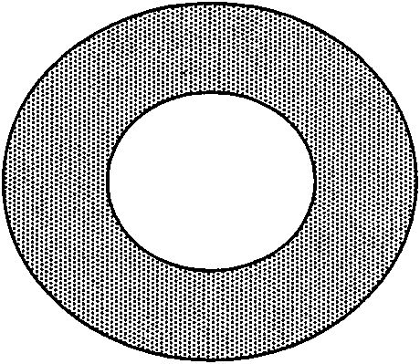
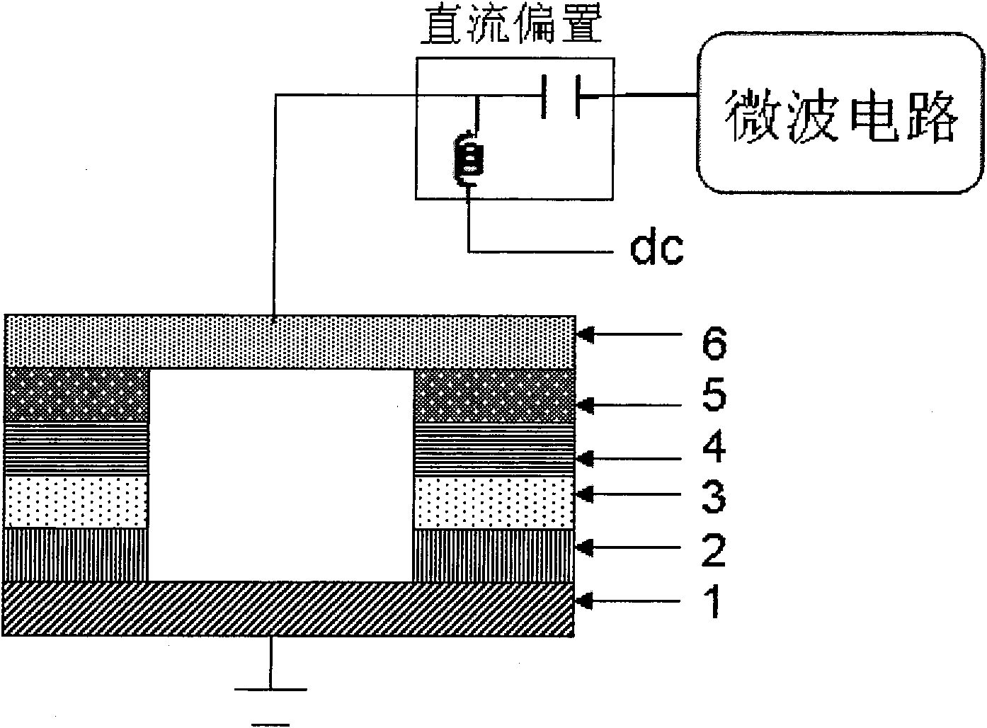
[0056] Figure 1-2 It is a schematic diagram of a spin microwave oscillator based on a non-pinning single-barrier circular magnetic multilayer film structure. From Figure 1-2 It can be seen that the spin microwave oscillator includes a non-pinning single-barrier annular magnetic multilayer film (such as Figure 1-1a ), DC bias (bias T) and microwave circuits. Wherein the DC bias includes a capacitor and an inductor, which are used to provide the DC current required for the work of the non-pinning type single-barrier annular magnetic multilayer film, and to pass the alternating signal; the microwave circuit includes an amplifier circuit, Filtering circuits and microwave antennas (not shown) are used to amplify and filter alternating signals and transmit microwave signals.

[0057] We use high-vacuum magnetron sputtering equipment under certain growth conditions, in the 1mm thick SrTiO cleaned by conventional methods 3 The lower buffer conductive layer Au with a thickness of...

Embodiment 2~4

[0062] The closed-shaped magnetic multilayer films of Examples 2-4 are obtained according to the method of Example 1 to obtain a spin microwave oscillator, and its working principle is the same as that described in Example 1. The closed magnetic multilayer films used in Examples 2-4 are listed in Table 1.

[0063] The closed shape magnetic multilayer film adopted in the embodiment 2-4 of table 1

[0064] Example

Embodiment 5

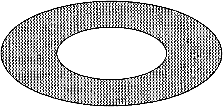
[0066] Figure 2-2 It is a schematic diagram of a spin microwave oscillator based on a non-pinning single-barrier circular magnetic multilayer film structure containing a metal core. The spin microwave oscillator includes a non-pinning single-barrier annular magnetic multilayer film containing a metal core, a DC bias, an external circuit dc2 and a microwave circuit, wherein the metal core is located in the geometry of the annular magnetic multilayer film central location (such as Figure 2-1a ). It should be noted that the shape of its cross section matches the shape of the magnetic multilayer film, that is, if the patterned shape of the magnetic multilayer film is an elliptical ring, the metal core is also elliptical (such as Figure 2-1b )

[0067] We use high-vacuum magnetron sputtering equipment under certain growth conditions, in the 1mm thick LaAlO cleaned by conventional methods 3 On the substrate, a lower buffer conductive layer Ru with a thickness of 30 nm, a hard...


PUM


Abstract

The invention provides a spin microwave oscillator and a spin microwave detector. The spin microwave oscillator of the invention is directly controlled by direct current based on microwave oscillationand output of a spin angle momentum transfer principle, or jointly regulated and controlled by direct current and impressed static magnetic field, has the advantages of miniaturization, high integration, low power consumption, high controllability and tunability and the like. The spin microwave detector of the invention directly detects input microwave by direct voltage generated by the input microwave, and has the advantage of direct measurement on high-frequency signals in no need of hybrid frequency.

Description

technical field [0001] The invention relates to the field of microwave oscillators and microwave detectors, in particular to spin microwave oscillators and spin microwave detectors based on closed magnetic multilayer films and closed magnetic multilayer films containing metal cores. Background technique [0002] There are already many commercial microwave oscillators on the market at present, but all of them have some shortcomings. For example, the magnetron oscillator was applied relatively early, but it is too large, not easy to integrate, and has low frequency and high power consumption, so it cannot be used for future communications; the frequency of the LC voltage-controlled oscillator is not high, almost It cannot reach gigahertz, and the frequency modulation range is relatively narrow, the integration level is low, and the quality factor is also low; the output frequency of crystal oscillators generally does not exceed 200MHz. Although the frequency stability is relat...

Claims


Application Information

Patent Timeline
Patent Type & Authority Applications(China)
IPC IPC(8): H01P7/10G01R29/00
Inventor 王译于国强刘东屏温振超韩秀峰
Owner INST OF PHYSICS - CHINESE ACAD OF SCI
Why Eureka
Try Eureka